Vacuum adsorption jig

A vacuum adsorption and jig technology, applied in the jig field, can solve problems such as affecting work efficiency, affecting flatness, glass deformation, etc., to achieve the effect of improving efficiency, uniform force, and avoiding bending

Pending Publication Date: 2018-11-13
ZHEJIANG SUNNY OPTICAL CO LTD
View PDF10 Cites 0 Cited by
  • Summary
  • Abstract
  • Description
  • Claims
  • Application Information

AI Technical Summary

Problems solved by technology

In the traditional technology, the glass can be transported through the suction nozzles arranged in an array, but because the suction nozzles are independent of each other, it is easy to cause deformation of the glass when it is absorbed, which affects the flatness, or it can also be transported through a vacuum adsorption fixture, but usually the glass is removed from the treatment When detaching from the jig, the vacuum environment in the jig needs to disappear before the glass can be detached from the jig, which affects work efficiency

Method used


Image

  • Vacuum adsorption jig
  • Vacuum adsorption jig
  • Vacuum adsorption jig

Examples


Embodiment approach

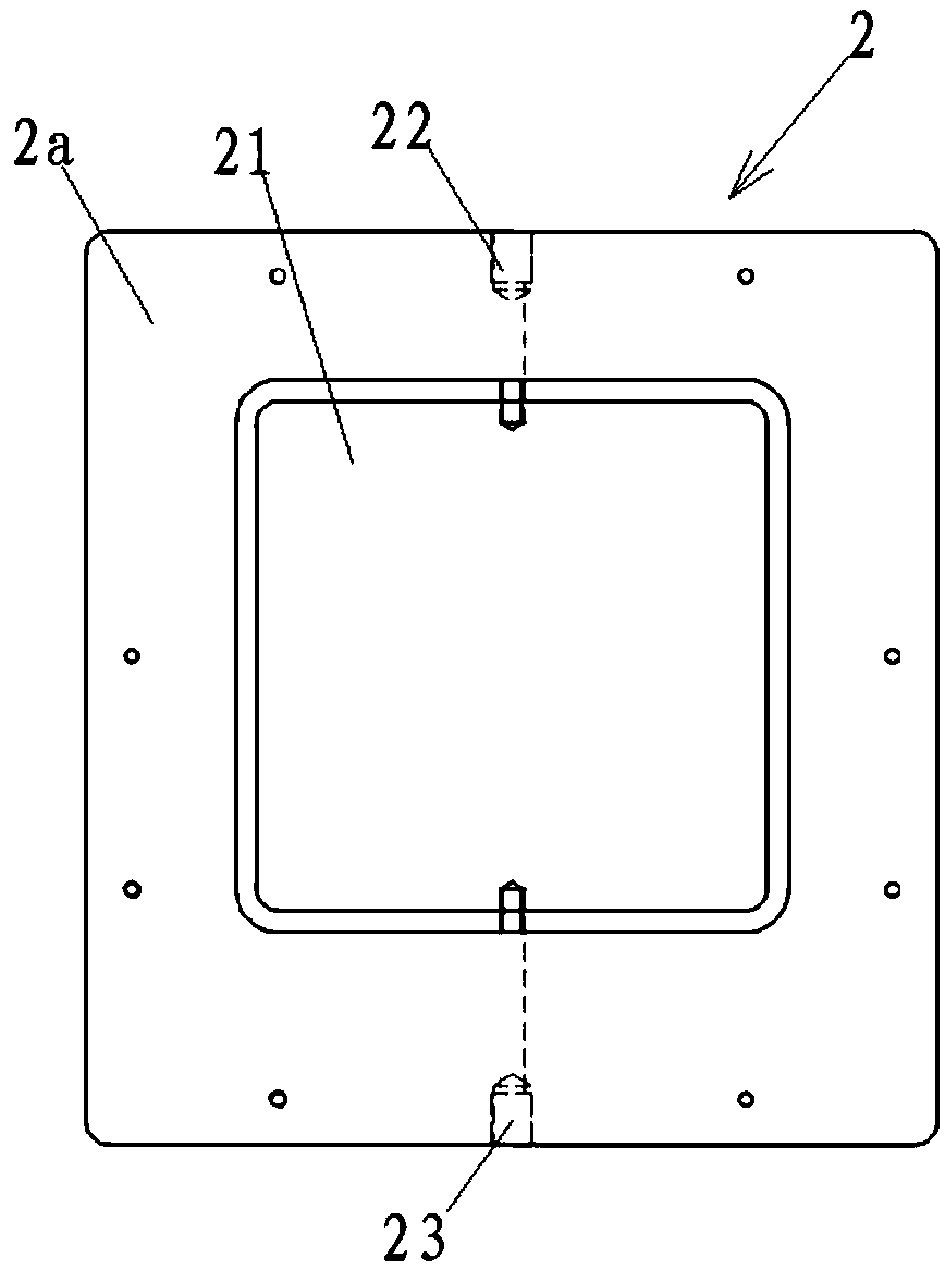
[0044] According to an embodiment of the present invention, the substrate 2 is provided with a first annular sealing structure, and the orifice plate 1 is provided with a second annular sealing structure matching the first annular sealing structure. In this embodiment, at least one first annular sealing structure is provided, and is arranged around the groove 21 . In this embodiment, the first annular sealing structure is an annular boss or an annular groove, and the corresponding second annular sealing structure is an annular groove or an annular boss. Through the joint connection between the first ring-shaped sealing structure and the second ring-shaped sealing structure, the sealing of the connection position between the orifice plate 1 and the substrate 2 is ensured, and air leakage at the connection position between the orifice plate 1 and the substrate 2 is avoided. , thereby ensuring that the material on the orifice plate 1 is stably adsorbed, thereby ensuring that the ...


PUM


Abstract

The invention relates to a vacuum adsorption jig which comprises a hole plate and a base plate. The hole plate is provided with through holes in an array mode, the base plate is provided with a groove, the hole plate and the base plate are mutually connected, and the through holes communicate with the groove mutually. The base plate is further provided with an air suction hole used for extractingair from the groove and an air conveying hole used for conveying air to the groove. The air suction hole is mutually connected with the an external air extraction device, air in the groove can be extracted out through the air extraction device, therefore, the groove forms a vacuum environment, and the through holes communicating with the groove adsorb materials located on the upper surface of thehole plate. It is ensured that all positions of materials can be supported on the upper surface of the hole plate, and material flatness is ensured. The air conveying hole is mutually connected with an air source device, air can be conveyed into the groove through the air source device, therefore, the materials in the adsorbed state can be rapidly disengaged from the hole plate, and the materialscan be conveniently taken down.

Description

technical field [0001] The invention relates to a jig, in particular to a vacuum adsorption jig. Background technique [0002] In the production process of lens inspection, the performance of the lens has high requirements on the accuracy of the cooperation between the inspection trays, and the gap between the two is very small, so the accuracy requirements of the fixture are very important. According to the optical design test requirements, it is necessary to attach a piece of glass flatly on the test tray to support the tested lens. In the process of attaching the glass to the test tray, the process and glass flatness requirements are very high. While ensuring the parallelism of the tray It is necessary to ensure the parallelism of the glass and the parallelism after the glass is attached to the tray. Therefore, before attaching the glass to the test tray, it is necessary to ensure the flatness of the glass on the jig during transportation, and that the glass can be quick...

Claims


Application Information

Patent Timeline
Patent Type & Authority Applications(China)
IPC IPC(8): B25B11/00G03B43/00G01M11/02
CPCG03B43/00G01M11/02G01M11/0214B25B11/00B25B11/005
Inventor 张炯飞
Owner ZHEJIANG SUNNY OPTICAL CO LTD
Why Eureka
Try Eureka