Double-shaft horizontal type mixer for mixing concrete

A double-shaft horizontal mixer technology, which is applied to cement mixing devices, clay preparation devices, liquid ingredient supply devices, etc., to achieve good mixing effects, improve reliability, and prevent agglomeration

Inactive Publication Date: 2018-11-13
高碑店市天筑新型建材有限公司
View PDF5 Cites 5 Cited by
  • Summary
  • Abstract
  • Description
  • Claims
  • Application Information

AI Technical Summary

Problems solved by technology

[0004] The invention proposes a double-shaft horizontal mixer for mixing concrete, which solves the technical problem in the prior art that the structure of the mixing mechanism affects the mixing effect due to the poor internal environment of the silo.

Method used


Image

  • Double-shaft horizontal type mixer for mixing concrete
  • Double-shaft horizontal type mixer for mixing concrete
  • Double-shaft horizontal type mixer for mixing concrete

Examples


Embodiment 1

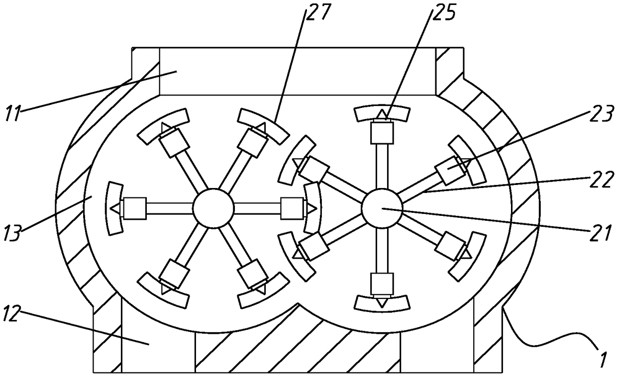
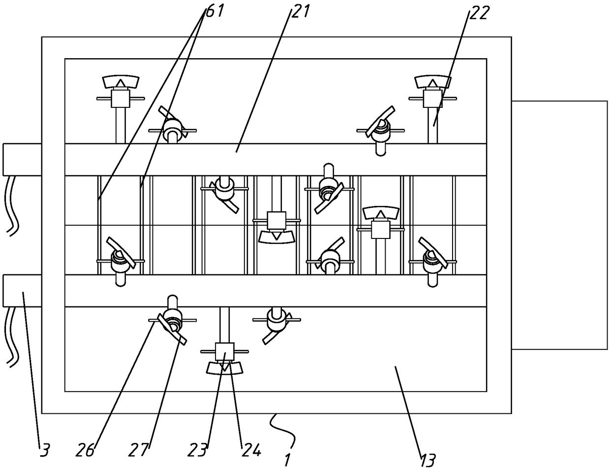
[0055] Such as Figure 1 ~ Figure 2 As shown, a double-shaft horizontal mixer for mixing concrete includes a casing 1, a silo 13 is arranged inside the casing 1, a material inlet 11 is arranged above the casing 1, and a discharge port is arranged below the casing 1 12. Both the material inlet 11 and the material outlet 12 are connected to the silo 13, and the inside of the hopper 13 is provided with a stirring spindle 21, and a number of stirring rods 22 are arranged on the stirring spindle 21 along its radial direction, and the stirring spindle 21 is a hollow structure Cavity 1 is formed inside, and one end of cavity 1 is sealed and the other end is connected to the liquid supply pump through rotary joint 3. The stirring rod 22 is a hollow structure and cavity 2 is formed inside, and cavity 2 communicates with cavity 1.

[0056] The stirring rod 22 is provided with a plurality of through holes 1 221, the through holes 1 221 are connected to the cavity 2, and the stirring rod ...

Embodiment 2

[0060] Such as Figure 1 to Figure 5 As shown, the stirring rod 22 is provided with several switch rods 41 along the longitudinal section, and the middle of the switch rod 41 is hinged with the stirring rod 22,

[0061] The gap between the stirring block 23 and the stirring rod 22 is less than the length of the stirring rod 22 when the switch rod 41 is perpendicular to the outer wall of the stirring rod 22,

[0062] Stirrer rod 22 interior sliding is provided with some switch sleeves 42, is provided with some through holes 43 on the switch sleeve 42,

[0063] The stirring rod 22 is also provided with a self-righting device 5,

[0064] When the stirring block 23 does not slide to the switch rod 41, the automatic righting device 5 keeps the direction of the switch rod 41 consistent with the radial direction of the stirring rod 22, and the second through hole 43 is not connected to the first through hole 221.

[0065] When the stirring block 23 slides to the switch lever 41 , p...

Embodiment 3

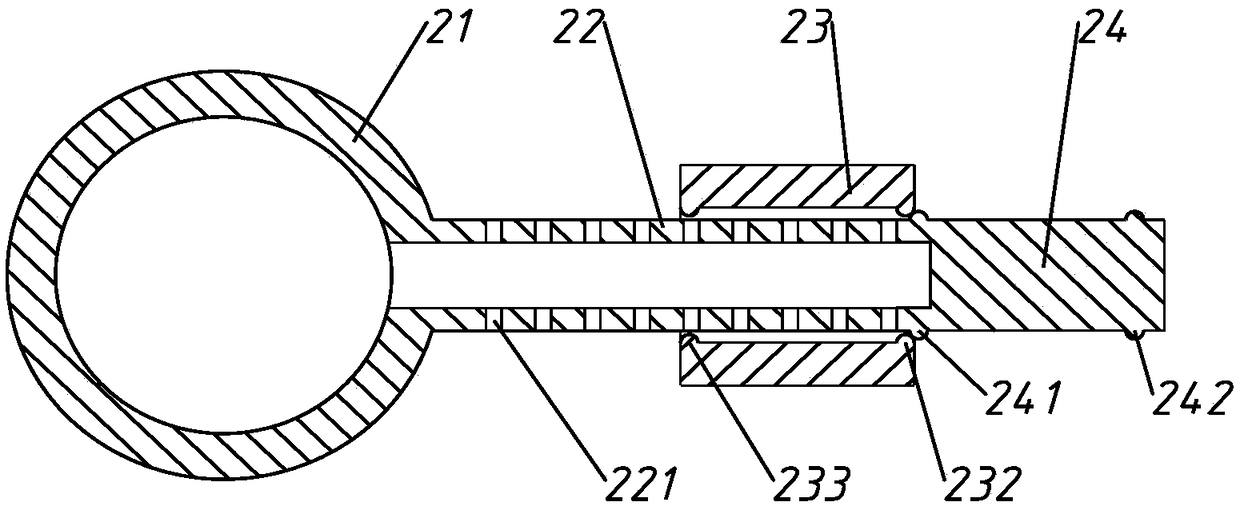
[0076] Such as Figure 1 ~ Figure 3 As shown, the far end of the stirring rod 22 from the stirring main shaft 21 is connected to one end of the connecting rod 24, the outer diameter of the stirring rod 22 is consistent with the outer diameter of the connecting rod 24, and the other end of the connecting rod 24 is provided with a limiting block 25, and the outer diameter of the limiting block 25 is greater than the inner diameter of the stirring block 23, the stirring rod 22, the connecting rod 24 and the limit block 25 are collinearly arranged,

[0077] The connecting rod 24 is circumferentially provided with a protruding edge 241 on the outer side near the limit block 25; Both the second convex edge 232 are made of elastic material, and the inner diameter of the second convex edge 232 is larger than the outer diameter of the connecting rod 24 and smaller than the outer diameter of the first convex edge 241 .

[0078] In this embodiment, when working, when the stirring liquid...


PUM


Abstract

The invention belongs to the technical field of mixers, and provides a double-shaft horizontal type mixer for mixing concrete. The double-shaft horizontal mixer comprises a machine shell, a stock binis arranged inside the machine shell, a feeding inlet is formed in the upper part of the machine shell, and a discharge port is formed in the lower part of the machine shell. The feeding inlet and thedischarge port both communicate with the stock bin, and mixing main shafts are rotatably arranged in the stock bin. The mixing main shafts are each provided with a plurality of mixing rods in the radial direction of the mixing main shafts, the mixing main shafts are of hollow core structures, and first cavities are formed in the inner portions of the mixing main shafts. One ends of the first cavities are sealed, and liquid supply pumps are connected to the other ends of the first cavities through rotary joints. The mixing rods are of hollow core structures, and second cavities are formed in the inner portions of the mixing rods. The first cavities communicate with the second cavities. The mixing rods are each provided with a plurality of first through holes, and the first through holes communicate with the second cavities. Mixing blocks are slidably arranged on the mixing rods. Through the double-shaft horizontal mixer, the technical problem that the mixing effect is affected due to the fact that the structure of a mixing mechanism of a mixer in the prior art is limited due to the poor internal environment of a stock bin is solved.

Description

technical field [0001] The invention belongs to the technical field of mixers, and relates to a double-shaft horizontal mixer used for mixing concrete. Background technique [0002] The double-shaft horizontal mixer is an efficient mixer. It has the advantages of compact structure, good sealing, preventing water mist from flowing back, even mixing, low noise, simple maintenance and low cost. Moreover, the stirring blade is fan-shaped, and the contact area with the medium is large during stirring. It is a relatively general stirring equipment and can be used in many powder production industries. [0003] However, in the application process of the double-shaft horizontal mixer, the environment with the mixer silo is harsh, the stirring blades on the agitator shaft are all fixed, and there is no other stirring mechanism in the silo of the mixer, which limits the mixing effect of the mixer. , At the same time, because the mixer usually uses the top water supply, resulting in u...

Claims


Application Information

Patent Timeline
Patent Type & Authority Applications(China)
IPC IPC(8): B28C5/14B28C7/12B28C5/08
CPCB28C5/0806B28C5/146B28C7/126
Inventor 来庚强
Owner 高碑店市天筑新型建材有限公司
Why Eureka
Try Eureka