Automatic demolding and trimming PP plastic part forming equipment and process

A technology for automatic demoulding and molding equipment, which is applied to household components, household appliances, and other household appliances. It can solve the problems of easy damage to the surface of the table, labor-intensive, manual operation, etc., to achieve clean and thorough cutting, and improve effect of effect

Active Publication Date: 2018-11-13
ZHEJIANG LIFAN FURNITURE
View PDF2 Cites 6 Cited by
  • Summary
  • Abstract
  • Description
  • Claims
  • Application Information

AI Technical Summary

Problems solved by technology

[0004] One of the purposes of the present invention is to provide a PP plastic parts molding equipment for automatic demoulding and edge trimming in view of the deficiencies of the prior art, which can be achieved by setting a discharge device and using negative pressure to absorb the edge waste of the table. The formed table board is quickly demoulded and taken out from the forming device to one side, and the removed table board is quickly and automatically cut off edge waste by setting the trimming device, and the entire demoulding and retrieving process is realized. Automation, and at the same time, it will not cause damage to the formed table during the process of retrieving the material, thereby solving the problem of low demoulding efficiency during the molding process of the plastic table, and the need for manual operation when the material is discharged, which is inefficient and labor-intensive , the surface of the table board is easily damaged during the discharging process, and it is inconvenient to cut the edge waste of the table board, the cutting effect is poor and the efficiency is low

Method used


Image

  • Automatic demolding and trimming PP plastic part forming equipment and process
  • Automatic demolding and trimming PP plastic part forming equipment and process
  • Automatic demolding and trimming PP plastic part forming equipment and process

Examples


Embodiment 1

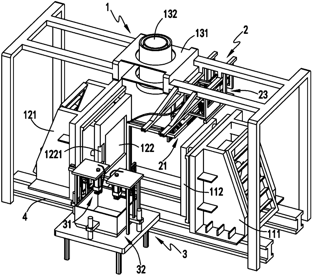
[0051] Such as figure 1 , figure 2 , image 3 , Figure 4 , Figure 5 , Figure 6 , Figure 7 , Figure 8 , Figure 9 , Figure 10 , Figure 11 , Figure 12 As shown, a PP plastic part molding equipment for automatic demoulding and trimming includes a molding device 1, and the molding device 1 includes a punch mechanism 11, a concave mold mechanism 12 that is formed in cooperation with the punch mechanism 11, and is arranged on a convex mold mechanism. The injection mechanism 13 above between the die mechanism 11 and the die mechanism 12; also includes the discharge device 2 arranged on one side of the injection mechanism 13 and the trimming device arranged on the same side of the punch mechanism 11 and the die mechanism 12 3;

[0052] The discharge device 2 includes a fixing mechanism 21 for absorbing and fixing the side waste 101 of the table 10 that has been formed and left on the die mechanism 12, and for driving the fixing mechanism 21 and the table 10 absorbe...

Embodiment 2

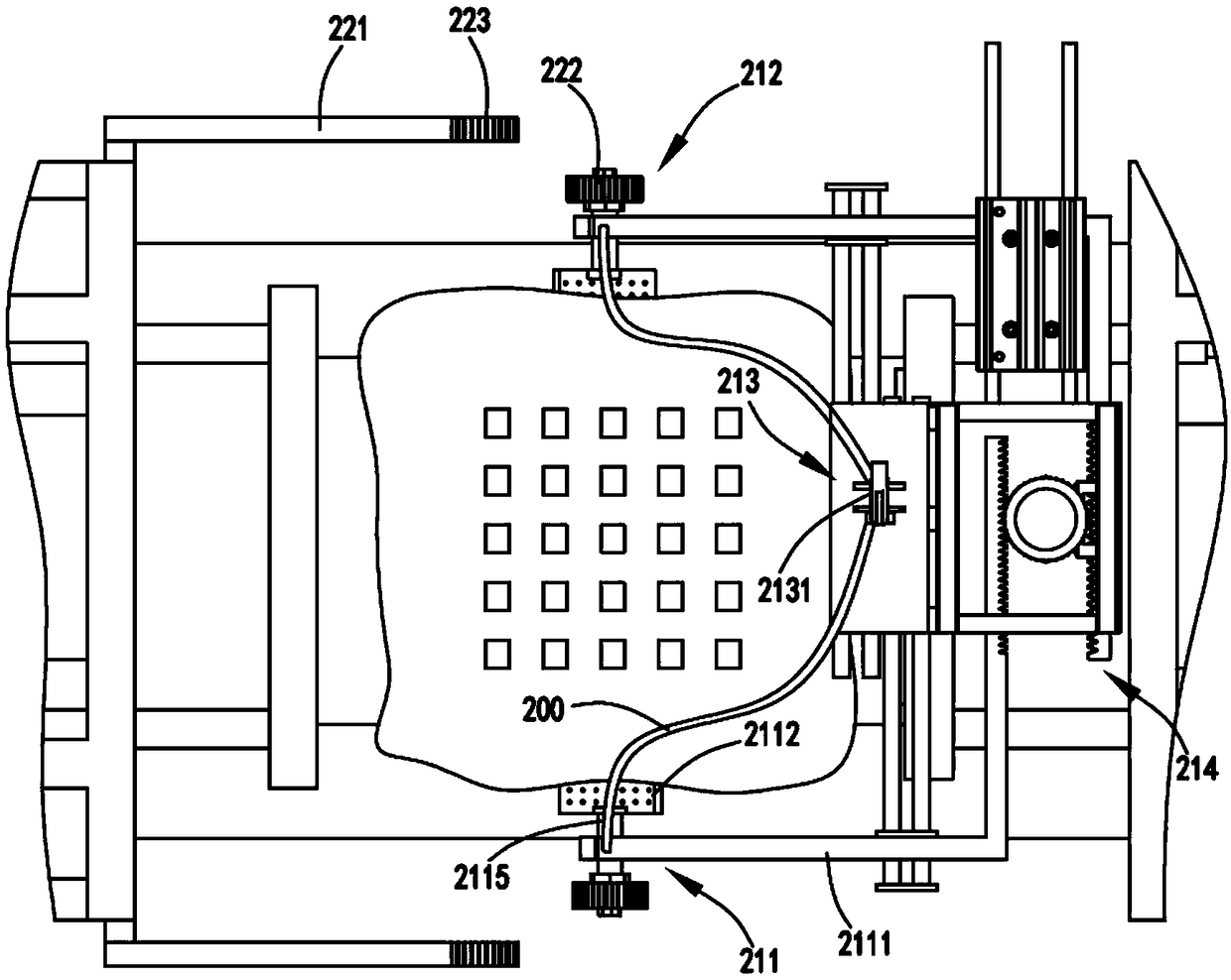
[0069] Such as figure 1 , figure 2 , image 3 , Figure 4 , Figure 5 , Figure 6 , Figure 7 , Figure 8 , Figure 9 , Figure 10 , Figure 11 , Figure 12As shown, the components that are the same as or corresponding to those in the first embodiment are marked with the corresponding reference numerals in the first embodiment. For the sake of simplicity, only the differences from the first embodiment will be described below. The difference between the second embodiment and the first embodiment is that the turning mechanism 22 includes a driving member 221 fixed on the die frame 121 and a third gear 222 fixed on the rotating shaft 2115 and arranged coaxially with the rotating shaft 2115, The end of the driving member 221 is provided with a rack portion 223 that cooperates with the third gear 222 , and the rack portion 223 drives the third gear 222 together with the adsorption plate 2112 to rotate 90° during the opening process of the die frame 121 .

[0070] In thi...

Embodiment 3

[0072] Such as Figure 13 As shown, a PP plastic part molding process with automatic demoulding and trimming includes the following production steps:

[0073] a. Forming process, the injection mechanism 13 extrudes the raw material to the forming station, and the punch mechanism 11 and the die mechanism 12 cooperate to extrude the raw material at the forming station;

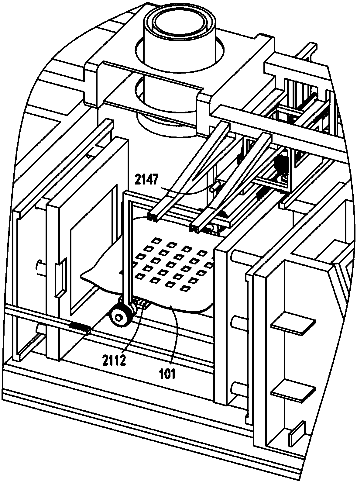
[0074] b. demoulding process, the punch mechanism 11 and the die mechanism 12 are opened to a certain position, and the fixing mechanism 21 utilizes the negative pressure adsorption force to absorb and fix the edge waste 101 of the table 10 left on the die mechanism 12, The punch mechanism 11 and the die mechanism 12 continue to open the mold, and the table plate 10 breaks away from the die mechanism 12;

[0075] c. Overturning process, during the mold opening process of the punch mechanism 11 and the concave mold mechanism 12, the overturn mechanism 22 drives the two adsorption components of the fixing mechani...


PUM


Abstract

The invention relates to automatic demolding and trimming PP plastic part forming equipment and a process. The equipment comprises a forming device which comprises a convex mold mechanism, a concave mold mechanism and a material injection mechanism arranged above the position between the convex mold mechanism and the concave mold mechanism. The equipment also comprises a discharging device arranged on one side of the material injection mechanism and a trimming device arranged on the same side of the convex mold mechanism and the concave mold mechanism. The discharging device comprises a fixingmechanism which adsorbs and fixes leftover materials of a desk plate, an overturning mechanism which drives the fixing mechanism to overturn to be in a flatwise state together with the desk plate anda moving-out mechanism which drives the fixing mechanism to be moved out to reach the trimming device together with the desk plate; the trimming device comprises a push-down mechanism which pushes the desk plate to move downwards vertically and settles the material flash wastes of the desk plate and a cropping mechanism which crops the leftover materials in the reset process of the push-down mechanism. The equipment provided by the invention solves the problems that a plastic desk plate is low in forming and demolding efficiency, the equipment is low in efficiency and wastes labor as a resultof manual operation needed by discharge, the surface of the desk plate is easily damaged and the leftover materials of the desk plate are inconveniently cropped in the discharging process, and the cropping effect is poor and the efficiency is low.

Description

technical field [0001] The invention relates to the technical field of plastic part forming equipment, in particular to a PP plastic part forming equipment and process for automatic demoulding and trimming. Background technique [0002] Many products used in life are plastic products. Some existing table tops are also formed by plastic blow molding. During the molding process of the table tops, there are often waste edges at the corners. To clean up the waste edge, in the prior art, the waste edge is generally cut off manually using a cutter, which not only consumes manpower but also has poor cutting effect, easily hurts the table board, and is inefficient. [0003] Aiming at the low degree of automation, poor cutting effect and low efficiency of plastic table waste edge removal, it is urgent to design a device to realize the rapid and automatic removal of table waste edge, improve its efficiency, and improve the waste edge removal while liberating manpower. The effect guar...

Claims


Application Information

Patent Timeline
Patent Type & Authority Applications(China)
IPC IPC(8): B29C45/17B29C45/33B29C45/40B29C37/02B29L31/44
CPCB29C37/02B29C45/1756B29C45/1769B29C45/33B29C45/4005B29L2031/448
Inventor 王泽凡王优杰王泽莉
Owner ZHEJIANG LIFAN FURNITURE
Why Eureka
Try Eureka