Continuous type regenerative braking system

A regenerative braking and rope technology, applied in sustainable transportation, climate sustainability, railway transportation, etc., can solve the problems of high stability requirements, large regenerative braking strokes, and difficult clutching, and achieve high stability requirements. , The effect of large regenerative braking stroke and improving operating efficiency

Pending Publication Date: 2018-11-13
卢军
View PDF7 Cites 0 Cited by
  • Summary
  • Abstract
  • Description
  • Claims
  • Application Information

AI Technical Summary

Problems solved by technology

It can be seen that the above-mentioned rope clutch is the clutch between the wire rope, the rope pile and the rope clutch, which is completely different from the clutch between the traditional driving shaft and the transmission shaft, and the rope clutch is in the guide chute. The direction of back-and-forth sliding in the center is opposite, so the order of clutching and disengaging with the rope is also reversed, but the direction of the steel wire rope pulling force from the energy storage spring is always the same, which results in a gap between the steel wire rope, the rope pile and the rope clutch. The working conditions faced by the clutch are completely different, and even multiple ropes participate in the clutch. In this case, it is very difficult to complete the clutch between the three at the same time. However, the system does not give how to realize the clutch between the three The specific structure and specific clutch method, so this kind of rope clutch does not actually exist in the current prior art
[0004] Secondly, the above-mentioned rope clutch only performs clutching on a group of energy storage spring groups in this system to complete a regenerative braking. The power and stroke are not enough. In view of the fact that the elastic force of the spring is proportional to the stroke, as the regenerative braking stroke increases, the change and drop of the regenerative braking force of a group of energy storage springs also increase, which cannot meet the needs of trains and high-speed rail vehicles. Or the characteristics of large regenerative braking strokes and high stability requirements for large carrier aircraft

Method used


Image

  • Continuous type regenerative braking system
  • Continuous type regenerative braking system
  • Continuous type regenerative braking system

Examples


Embodiment Construction

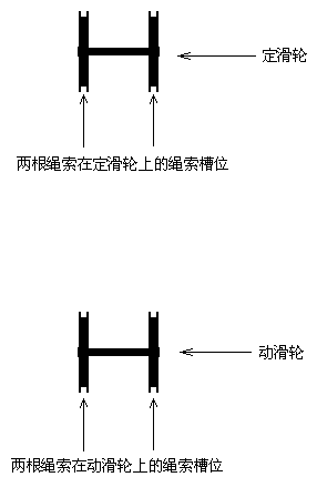
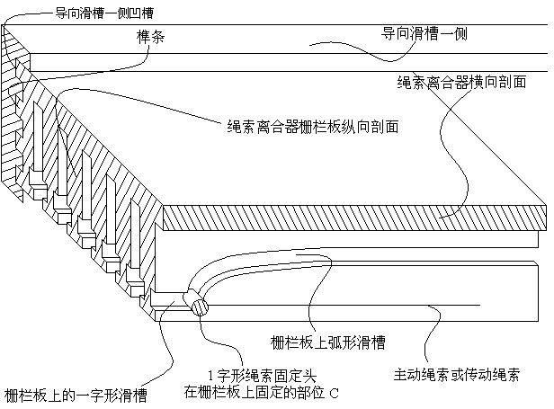
[0019] On the implementation of multi-rope crossover clutches in guide chutes. During the braking process, the multi-rope cross-connection clutch implements clutching between a transmission rope, a 2-shaped rope pile and the rope clutch. The one-shaped rope fixing head of a transmission rope is fixed on the A part of the two-shaped rope pile (such as Figure 6 ), when the rope clutch slides along the guide chute to the braking direction (such as Figure 4 ), the 2-shaped rope stake enters the rope clutch fence plate (such as Figure 7 ), the 1-shaped rope fixing head fixed on the A part of the 2-shaped rope pile enters the inline chute of the rope clutch, and is fixed on the C part of the rope clutch. When the rope clutch continued to slide towards the braking direction along the guide chute, the rope clutch would take the inline rope fixing head away from the 2-shaped rope pile, that is, the root drive rope was connected with the rope clutch.

[0020] Then, the multi-rope ...


PUM


Abstract

The invention provides a continuous type regenerative braking system. The continuous type regenerative braking system is base on the characteristics of demand of large regenerative braking distance and high stability requirements of trains, high-speed rail vehicles or large carrier aircraft, and adopts a multi-rope cross-connection clutch to complete the continuous regenerative braking by using multiple energy storage groups as continuous energy storage and energy releasing energy.

Description

technical field [0001] The invention relates to regenerative braking technology, in particular to a continuous regenerative braking system using multiple energy storage groups as continuous energy storage or energy release. Background technique [0002] At present, there is a known external regenerative braking system with wide applicability and dual-use for both military and civilian use. Its patent number is 2015101158411. The opposite characteristics, establish the basic mode of braking-starting-energy storage, and set and use wire ropes, blocking connectors, starting connectors, rope clutches, rope splitters, servos, rope chutes, guide pulleys, guide slides Slots and other configurations, the steel wire rope bypasses the guide pulley for steering adjustment, and the blocking connector, starting connector and energy storage spring group are connected in series to form a series of the most basic regenerative braking systems. Thus, combined with the system figure 2 It can...

Claims


Application Information

Patent Timeline
Patent Type & Authority Applications(China)
IPC IPC(8): B61D43/00B64F1/02
CPCB61D43/00B64F1/02Y02T30/00
Inventor 卢军
Owner 卢军
Why Eureka
Try Eureka