Voltage sensor and method for measuring voltage using the same

A voltage sensor and a technology for measuring voltage, applied in the field of sensors, can solve the problems of high cost, high requirements on polarization stability of light source and optical path system, poor temperature stability and environmental stability, and achieve low cost, high stability, adaptability strong effect

Active Publication Date: 2018-04-06
CHINA ELECTRONIC TECH GRP CORP NO 38 RES INST
View PDF5 Cites 0 Cited by
  • Summary
  • Abstract
  • Description
  • Claims
  • Application Information

AI Technical Summary

Problems solved by technology

At present, the optical voltage sensor generally adopts the polarized light interference method based on the electro-optic effect, uses the electric field to modulate the polarization state of the light, and completes the extraction of the electric field signal through the polarization detection system, because this method is very sensitive and depends on the polarization characteristics of the entire optical path , the polarization stability of the light source and the optical path system is extremely demanding, and there are problems such as high cost, poor temperature stability and environmental stability.

Method used


Image

  • Voltage sensor and method for measuring voltage using the same
  • Voltage sensor and method for measuring voltage using the same

Examples


Embodiment 1

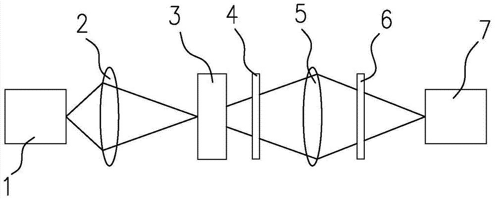
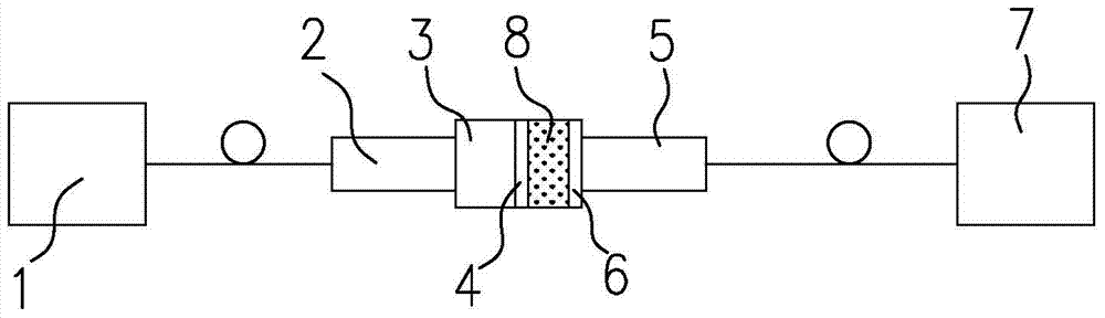
[0023] Such as figure 2 As shown, the voltage sensor of the present invention includes a monochromatic non-polarized light source 1, a first converging lens 2, an electro-optic sensor 3, a polarizer 4, a second converging lens 5, an aperture 6 and a photodetector 7, and a monochromatic non-polarized light source 1 The first converging lens 2 is connected by a multimode optical fiber, the first converging lens 2 is fixed on one side of the electro-optic sensor 3 by glue bonding, the other side of the electro-optic sensor 3 and one side of the polarizer 4 are fixed by glue bonding, and the polarizer The other side of the 4 is bonded and fixed with quartz glass 8, the other side of the quartz glass 8 is bonded and fixed with the diaphragm 6, and the other side of the diaphragm 6 is fixed with one side of the second converging lens 5 by glue bonding. The other sides of the two converging lenses 5 are connected to the photodetector 7 through another multimode optical fiber.

[00...

Embodiment 2

[0026] The difference between this embodiment and Embodiment 1 is that the positions of the diaphragm 6 and the second converging lens 5 are exchanged, the other side of the polarizer 4 is bonded and fixed with quartz glass 8, and the other side of the quartz glass 8 is bonded and fixed with the second Two converging lenses 5, the other side of the second converging lens 5 is bonded and fixed to one side of the diaphragm 6, and the other side of the diaphragm 6 is connected to the photodetector 7 through an optical fiber.

[0027] The present invention adopts the method for measuring voltage of above-mentioned voltage sensor, comprises the following steps:

[0028] (1) load the voltage to be measured on the electro-optic sensor 3,

[0029] (2) if figure 1 As shown, the light beam emitted by the monochromatic non-polarized light source 1 passes through the first converging lens 2 to form a converging light beam with a convergence angle of 30°-70° and enters the electro-optic s...


PUM


Abstract

The invention discloses a voltage sensor and a voltage measurement method by adopting the voltage sensor. The voltage sensor comprises a monochrome unpolarized light source, a first convergent lens, an electro-optical sensor, a polarization apparatus, a second convergent lens, a diaphragm and a photoelectric detector, wherein the monochrome unpolarized light source is connected with the first convergent lens through an optical fiber, the first convergent lens is fixed one side surface of the electro-optical sensor, the other side surface of the electro-optical sensor is fixed with one side surface of the polarization apparatus, the other side of the polarization apparatus is fixed with the diaphragm through quartz glass, the other side surface of the diaphragm is fixed with one side surface of the second convergent lens, and the other side surface of the second convergent lens is connected with the photoelectric detector through another optical fiber. The voltage sensor does not need a stable polarized system and a light source with the high polarized quality, and is strong in adaptability of the temperature and the environment and low in cost.

Description

technical field [0001] The invention relates to a sensor, in particular to a voltage sensor and a method for measuring voltage. Background technique [0002] With the gradual promotion and popularization of smart grids, the demand for voltage sensors or voltage transformers is increasing. At present, the optical voltage sensor generally adopts the polarized light interference method based on the electro-optic effect, uses the electric field to modulate the polarization state of the light, and completes the extraction of the electric field signal through the polarization detection system, because this method is very sensitive and depends on the polarization characteristics of the entire optical path , the polarization stability of the light source and the optical path system is extremely demanding, and there are problems such as high cost, poor temperature stability and environmental stability. Contents of the invention [0003] The purpose of the present invention is to p...

Claims


Application Information

Patent Timeline
Patent Type & Authority Patents(China)
IPC IPC(8): G01R19/00
Inventor 王昌雷陈信伟武帅
Owner CHINA ELECTRONIC TECH GRP CORP NO 38 RES INST
Why Eureka
Try Eureka