Aircraft landing gear frame stabilization buffer device and control method thereof

A technology of aircraft landing gear and buffer device, which is applied in the directions of landing gear, aircraft parts, transportation and packaging, etc., can solve the problems of inability to realize active adjustment of the position of the frame beam, danger, and reduced reliability and safety of aircraft landing gear. Achieve high reliability, easy maintenance, and improve reliability.

Active Publication Date: 2020-04-10
LANDING GEAR ADVANCED MFG
View PDF4 Cites 0 Cited by
  • Summary
  • Abstract
  • Description
  • Claims
  • Application Information

AI Technical Summary

Problems solved by technology

Invention patent CN103032403 introduces a frame position control actuator that can retract and retract the main landing gear frame at a large angle, which can realize the adjustment of the attitude of the frame beam and the follow-up with the ground load, but the failure of the hydraulic system is not considered Under the circumstances that the frame cannot be put down, it will be very dangerous for the aircraft to land with the frame retracted, which will reduce the overall reliability and safety of the aircraft landing gear
Although this type of frame stabilizing buffer device has a simple structure, it only realizes the dynamic buffering and damping function of the frame when the aircraft is sliding on the ground, and cannot realize the active adjustment of the position of the frame beam.

Method used


Image

  • Aircraft landing gear frame stabilization buffer device and control method thereof
  • Aircraft landing gear frame stabilization buffer device and control method thereof
  • Aircraft landing gear frame stabilization buffer device and control method thereof

Examples


Embodiment Construction

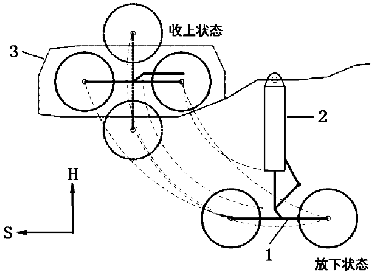
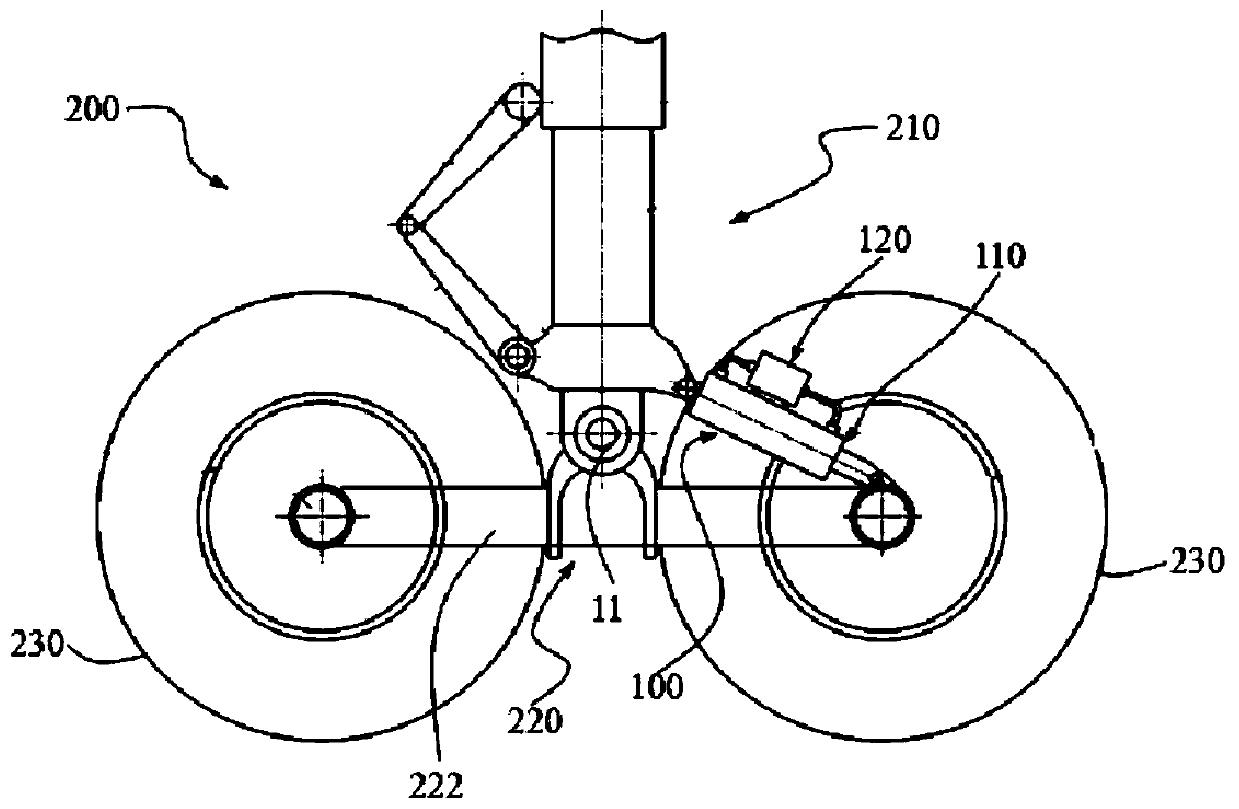
[0032] like Figure 2A , Figure 2B As shown, a frame stabilization buffer device 100 suitable for a large aircraft frame-type main landing gear system 200 proposed by the present invention includes an actuator for connecting the outer cylinder of the landing gear buffer strut 210 and the frame 220 - The cylinder assembly 110, the control element fixed on the cylinder assembly 110 - the hydraulic control valve assembly 120, and the necessary connecting pipes. The main landing gear involved in this application has a retractable function, and mainly includes: a retractable buffer strut 210, a frame 220 that can rotate around the hinge point 11, the frame 220 at least includes a frame beam 222, and the two ends of the frame beam 222 are generally Two or more pairs of wheels 230 are assembled.

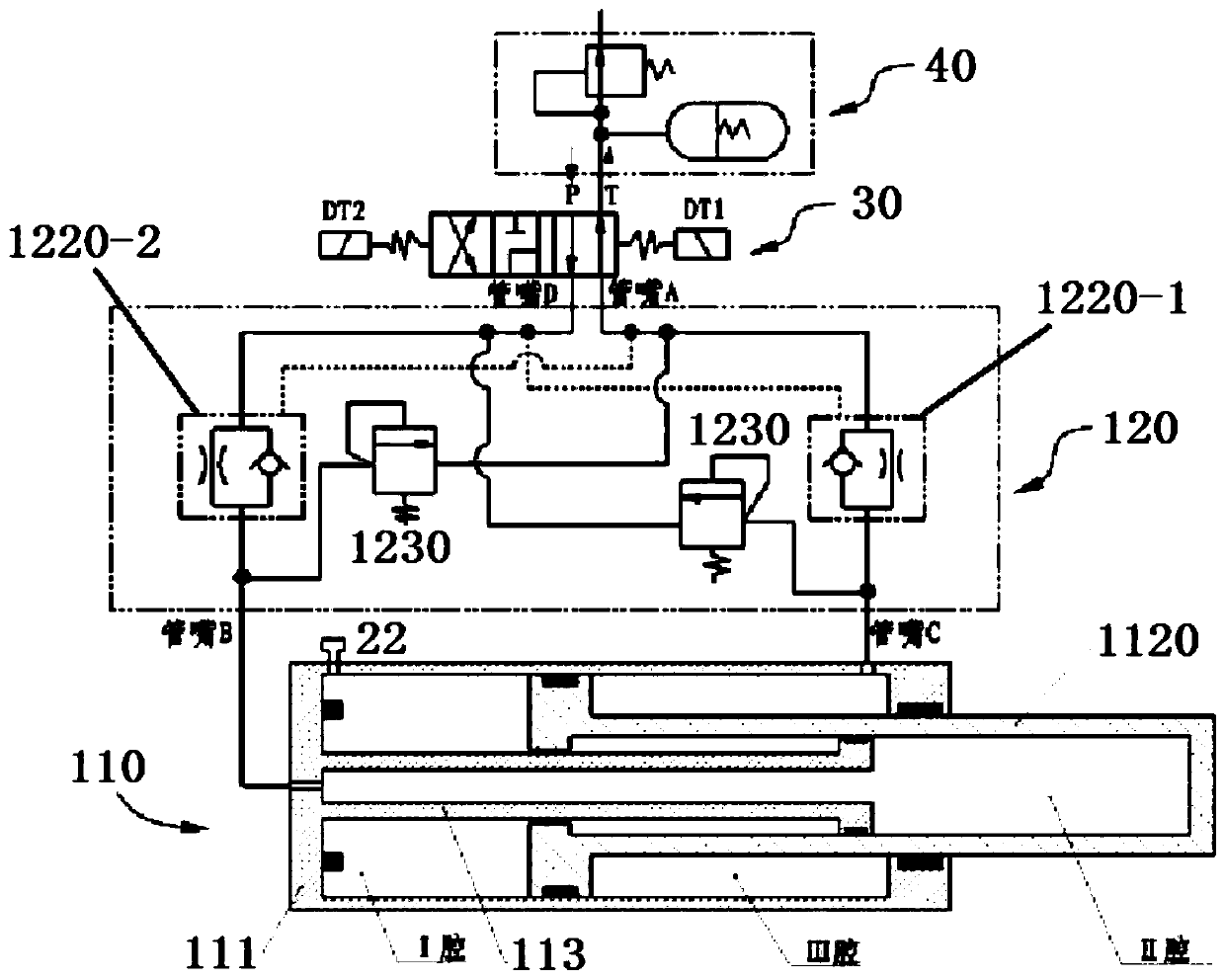
[0033] like image 3 As shown, the actuator assembly 110 includes: an outer cylinder 111, a piston rod 1120, a core rod 113, a guide bushing 114, a cylinder head 115, a hydraulic nozzle...


PUM


Abstract

The invention discloses an aircraft landing gear vehicle frame stabilizing buffer device and control method thereof. The aircraft landing gear vehicle frame stabilizing buffer device comprises an actuator cylinder assembly and a hydraulic control valve assembly, wherein the actuator cylinder assembly connects a landing gear buffer supporting column with a vehicle frame, and a piston rod of the actuator cylinder assembly is sleeved with an outer cylinder; core bars are sleeved with inner cavities of a cylinder cover and the piston rod so as to divide an inner cavity of the outer cylinder into acavity I which is served as an air cavity, a cavity II and a cavity III, wherein the cavity II and the cavity III are served as oil cavities; an cavity of the hydraulic control valve assembly is divided into a first cavity and a second cavity which are symmetrically arranged by a hydraulic control piston, and stepped faces and first and second one-way throttle valves are correspondingly disposedin the first and second cavities; a cavity I of the actuator cylinder assembly is filled with compressed gas, and a cavity II is connected with a cavity III by a three-position four-way solenoid valvewith a Y-type meso-position function; and an aircraft hydraulic oil passage P is connected with an oil inlet of the three-position four-way solenoid valve, and a system outlet oil line T is connectedwith an oil return port of the three-position four-way solenoid valve. The aircraft landing gear vehicle frame stabilizing buffer device and control method thereof realize the retracting and buffering damping of the vehicle frame and has the function of lowering in a backup mode.

Description

technical field [0001] The invention relates to a frame-type landing gear used in large aircraft, in particular to a stable buffer device used for retracting, buffering and damping of a small frame of an aircraft landing gear and a control method thereof. Background technique [0002] At present, the landing gear of large aircraft generally adopts the front three-point layout, and its main landing gear mostly adopts the configuration of a single strut with a multi-wheel frame arranged in the longitudinal direction. In order to reduce the flight resistance, the landing gear is usually designed to be retractable. : After the plane takes off, retract the landing gear into the fuselage or wing, and then lower the landing gear when landing. like figure 1 As shown, the movements of the landing gear retraction mechanism are mostly plane movements in the heading S and vertical H planes. If the landing gear is retracted in the attitude when it leaves the ground, that is, the angle b...

Claims


Application Information

Patent Timeline
Patent Type & Authority Patents(China)
IPC IPC(8): B64C25/22B64C25/58
CPCB64C25/22B64C25/58
Inventor 张航舟邓晓山路红伟慕建全金军刘庞轮陈永卿黄海清宁晓东李志愿樊建徐达生韩伟佳
Owner LANDING GEAR ADVANCED MFG
Why Eureka
Try Eureka