Material transfer box for sealing device and transfer method

A technology of closing device and transfer box, applied in the directions of capping, closing, packaging, etc., can solve the problem of time-consuming and labor-intensive, and achieve the effect of ensuring safety, wide application range, and convenient operation of the robotic arm.

Pending Publication Date: 2018-11-13
RES INST OF PHYSICAL & CHEM ENG OF NUCLEAR IND
View PDF5 Cites 10 Cited by
  • Summary
  • Abstract
  • Description
  • Claims
  • Application Information

AI Technical Summary

Problems solved by technology

[0004] The purpose of the present invention is to solve the time-consuming and labor-intensive problem of opening and closing the transfer box with a manipulator in the prior art, and to provide a material transfer bo

Method used


Image

  • Material transfer box for sealing device and transfer method
  • Material transfer box for sealing device and transfer method
  • Material transfer box for sealing device and transfer method

Examples


Embodiment 1

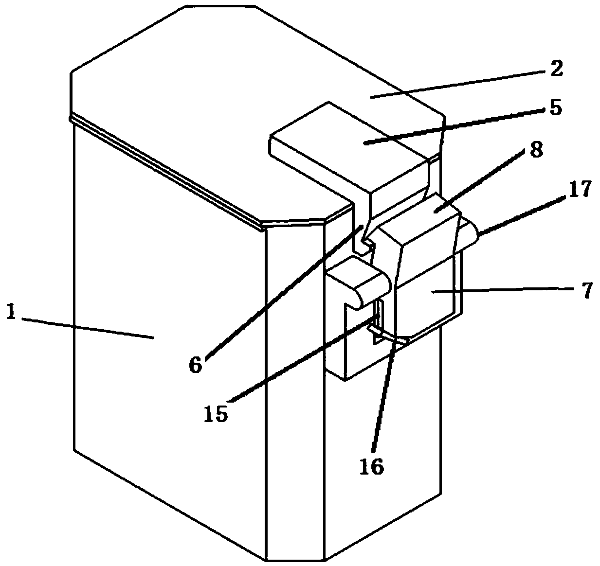
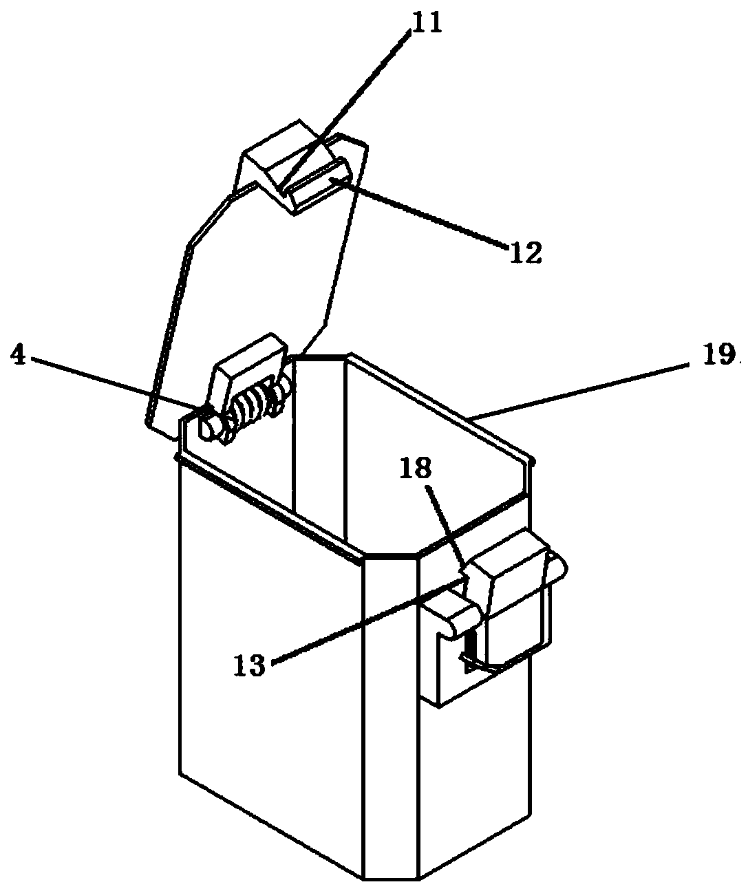
[0033] A material transfer box used in a closing device, comprising a box body 1 and a box cover 2 whose inner side is rotatably connected to the top of the box body 1 through a torsion shaft, and the outer side of the box cover 2 is fixed with an upper fixing part 5 and upper hook 6 constitute the upper lock, the outer side of the box body 1 is provided with a lower lock composed of the lower rotating part 7 and the lower hook 8 matching with the upper hook 6, the lower The rotating part 7 is rotationally connected with the box body 1 through a rotating shaft 9 , and a compression spring 10 is provided in the gap between the outer walls of the box body 1 of the lower rotating part 7 .

[0034] With the side close to the outer wall of the box body 1 as the inside and the side farther away from the outer wall of the box body 1 as the outside, the upper lock and the lower lock are arranged to facilitate the manipulator to open and close the box. When closing the box, the manipula...

Embodiment 2

[0040] In order to further optimize the shape and material of the transfer box, this embodiment is improved on the basis of embodiment 1.

[0041] As a preferred manner, the box cover 2 is rectangular or octagonal, and the transverse section of the box body 1 is rectangular or octagonal, which is convenient for the manipulator to grab and can accommodate materials of different sizes.

[0042] As a preferred manner, the bottom side wall of the box body 1 protrudes from the bottom of the box body 1 to form a grabbing edge 14, which is convenient for the manipulator to grab the material box after dumping the material.

[0043] As a preferred manner, the top edge of the box body 1 is provided with a grasping flange 19 to facilitate the grasping and transportation of the robot.

[0044] As a preferred manner, the box body 1 and the box cover 2 are made of metal materials.

Embodiment 3

[0046] In order to further optimize the structure of the lower locking member, this embodiment is improved on the basis of embodiment 1 or embodiment 2.

[0047] As a preferred mode, the bottom end of the lower rotating part 7 is provided with a draw-in groove 15 for engaging the free edge of the compression spring 10, and the outside of the draw-in groove 15 is welded with a limit piece 16 arranged obliquely to prevent the compression spring 10 from coming out. .


PUM


Abstract

The invention discloses a material transfer box for a sealing device. The material transfer box comprises a box body and a box cover with the inner side rotatably connected with the top of the box body through a torsion rotating shaft, an upper locking fit piece composed by an upper fixing part and an upper hook is fixedly arranged on the outer side of the box cover, a lower locking fit piece composed by a lower rotating part and a lower hook matched with the upper hook is arranged on the outer side of the box body, the lower rotating part is rotatably connected with the box body through a rotating shaft, and a compression spring is arranged in the gap between the outer wall of the box body and the lower rotating part. The mechanical arm can conveniently operate by arranging a switch on the side wall of the material box, by arranging a grabbing flip, the fact that the material box cannot fall off in the transporting process is ensured, the safety of the material in the transporting anddumping process of the material box is ensured, and meanwhile, the fact that the material can accurately enter a target container without loss is ensured.

Description

technical field [0001] The invention relates to the technical field of equipment related to material storage and transfer, in particular to a material transfer box used in a closed device and a transfer method. Background technique [0002] Some special industrial production and scientific experiments need to be carried out in a fully enclosed space isolated from the external environment. In this environment, all activities require the operation of mechanical arms and electric devices. Due to the limitation of the structure and function of the robotic arm, it is difficult to grasp some materials and parts with small size. If during some tests, frequent transportation and delivery of materials is required. At the same time, the material price is relatively high or has physical or chemical toxicity, which requires the material to be accurately put into the target container. During the delivery and transportation of materials, it is required to ensure that the materials will...

Claims


Application Information

Patent Timeline
IPC IPC(8): B65D43/16B65D55/02B65G47/90B65G65/23
CPCB65D43/164B65D55/02B65G47/90B65G65/23
Inventor 刘欢罗立平闫超
Owner RES INST OF PHYSICAL & CHEM ENG OF NUCLEAR IND
Why Eureka
Try Eureka