
a leaf spring

A technology of leaf springs and leaf springs, applied in the direction of springs, low internal friction springs, springs/shock absorbers, etc., can solve problems such as temperature rise of leaf springs, increased frictional force, and decreased comfort

Active Publication Date: 2019-06-21
NORTHEASTERN UNIV LIAONING
View PDF4 Cites 0 Cited by
  • Summary
  • Abstract
  • Description
  • Claims
  • Application Information

AI Technical Summary

Problems solved by technology

While the friction between the individual spring leaves provides damping, it is poorly controlled and causes stiction in the suspension movement
Make the occupant feel less comfortable when riding
And the damping performance of the leaf spring has been determined after its structure is determined and cannot be adjusted
[0004] In addition, the leaf spring forms a stretching motion when it is subjected to a load impact, and strong friction occurs between the spring sheets, that is, a phenomenon of extrusion and stretching occurs, and the two friction surfaces produce motion friction in two different directions, causing the temperature of the leaf spring to rise. When the load impact frequency increases, the frictional motion force generated by the stretching movement also increases, and when the stress concentration point reaches the fatigue limit, it will cause a single piece or the whole stack to break.

Method used


Image

  • a leaf spring
  • a leaf spring
  • a leaf spring

Examples


Embodiment Construction

[0028] In order to better explain the present invention and facilitate understanding, the present invention will be described in detail below through specific embodiments in conjunction with the accompanying drawings. The directional nouns such as "up" and "down" mentioned in this article are based on figure 1 The orientation in is for reference.

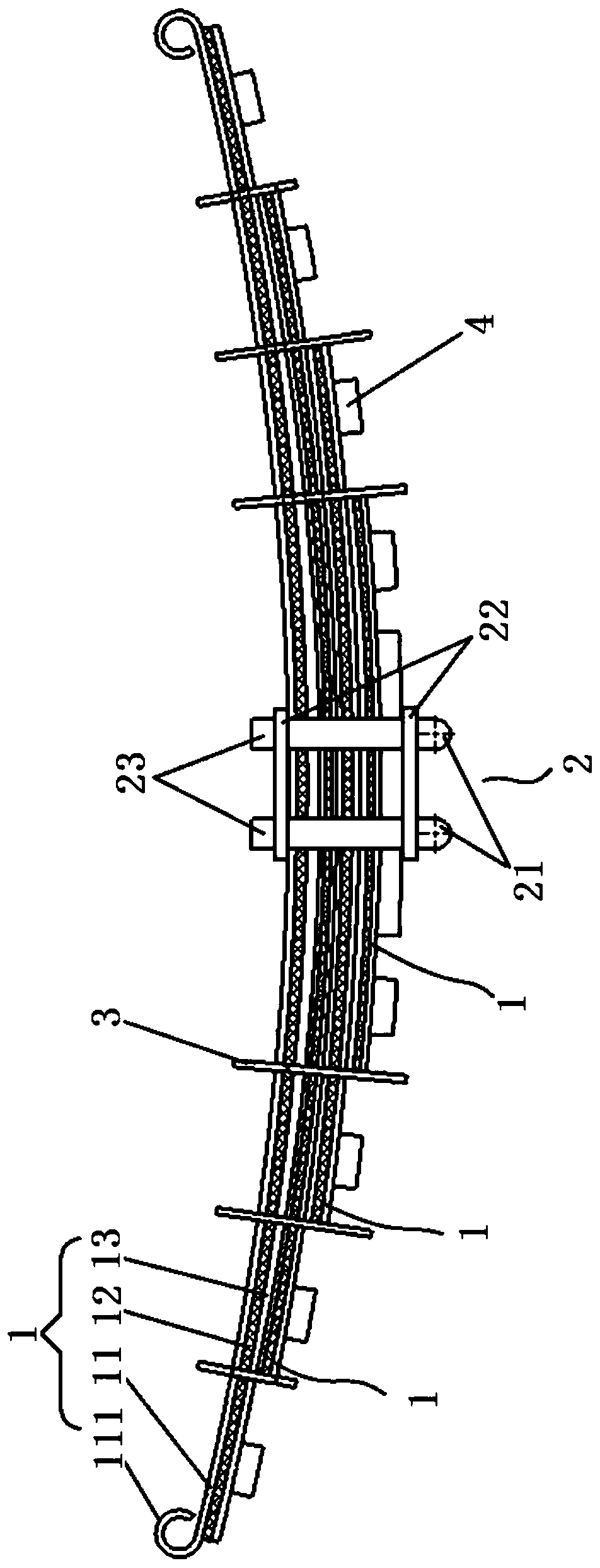
[0029] refer to Figure 1 to Figure 5 , the present embodiment provides a leaf spring, the whole shape of which is a downwardly protruding arc, specifically including a plurality of plate assemblies 1 , bolt assemblies 2 , a plurality of buckles 3 and a plurality of electromagnet assemblies 4 .

[0030] Wherein, a plurality of plate assemblies 1 are stacked up and down, and the lengths of the plurality of plate assemblies 1 decrease sequentially along the direction from top to bottom. Moreover, in every two adjacent panel assemblies 1 up and down, the two ends of the lower panel assembly 1 have the same indentation size relative t...


PUM


Abstract

The invention relates to a leaf spring with adjustable damping performance. Specifically, the overall shape of the leaf spring is a downwardly convex arc, including a plurality of plate assemblies stacked up and down, a bolt assembly fixed at the middle position of the plate assembly, and a plurality of clips spaced apart along the length direction of the leaf spring. buckle, and multiple electromagnet assemblies. Wherein, the lengths of the plurality of plate assemblies are successively reduced in the direction from top to bottom, and each plate assembly includes a first spring leaf, a sheet magnetorheological elastomer and a second spring leaf stacked from top to bottom; bolts The assembly and the plurality of buckles press the plurality of plate assemblies together, and an electromagnet assembly is fixed at both ends of the lower side of the second spring leaf in each plate assembly.

Description

technical field [0001] The present invention relates to a leaf spring. Background technique [0002] Buffering devices are needed in mechanical equipment to protect the machinery from being damaged by external shocks. As a typical cushioning component, the spring utilizes the elastic deformation of the object to absorb energy to achieve cushioning and shock absorption. [0003] The leaf spring is a long circular arc spring steel with a rectangular cross section. In the most common leaf spring configuration, the center of the arc provides the location of the axle, while lugs formed at either end attach to the vehicle chassis. For very heavy vehicles, a leaf spring can usually be made by stacking several tapering leaves together. Leaf springs can be used for positioning and have some degree of damping as well as spring function. While the friction between the individual leaf springs provides damping, it is poorly controlled and causes stiction in the suspension's motion. ...

Claims


Application Information

Patent Timeline
Patent Type & Authority Patents(China)
IPC IPC(8): F16F3/07
CPCF16F3/02
Inventor 宋万里孙振聪何春阳刁中洋彭珍
Owner NORTHEASTERN UNIV LIAONING
Learn More