Displacement ventilation dusting equipment used for workshop

A technology for replacing ventilation and dust removal equipment, which is applied to ventilation systems, mechanical equipment, lighting and heating equipment, etc. It can solve the problems of no self-cleaning structure of the dustproof filter, blockage of the filter, and influence on stability, so as to improve indoor air Excellent quality, dust reduction, and easy cleaning

Inactive Publication Date: 2018-11-13
马勇
View PDF0 Cites 8 Cited by
  • Summary
  • Abstract
  • Description
  • Claims
  • Application Information

AI Technical Summary

Problems solved by technology

[0003] However, the existing plant uses replacement ventilation and dust removal equipment. The dust-proof filter inside the blower does not have a self-cleaning structure. The filter is prone to clogging after long-term use, which affects its stability in use. Secondly, there is no purifier for the air discharged from the plant. The self-cleaning structur

Method used


Image

  • Displacement ventilation dusting equipment used for workshop
  • Displacement ventilation dusting equipment used for workshop
  • Displacement ventilation dusting equipment used for workshop

Examples


Embodiment 1

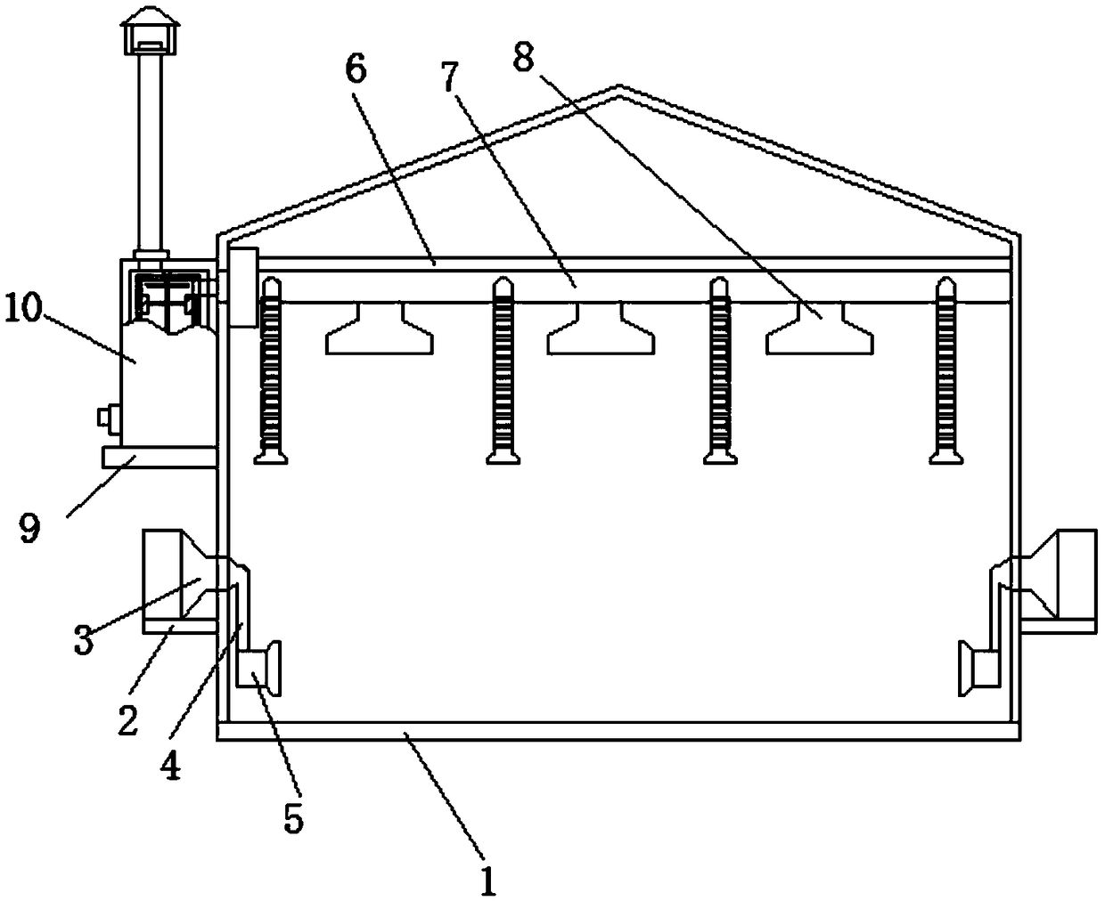
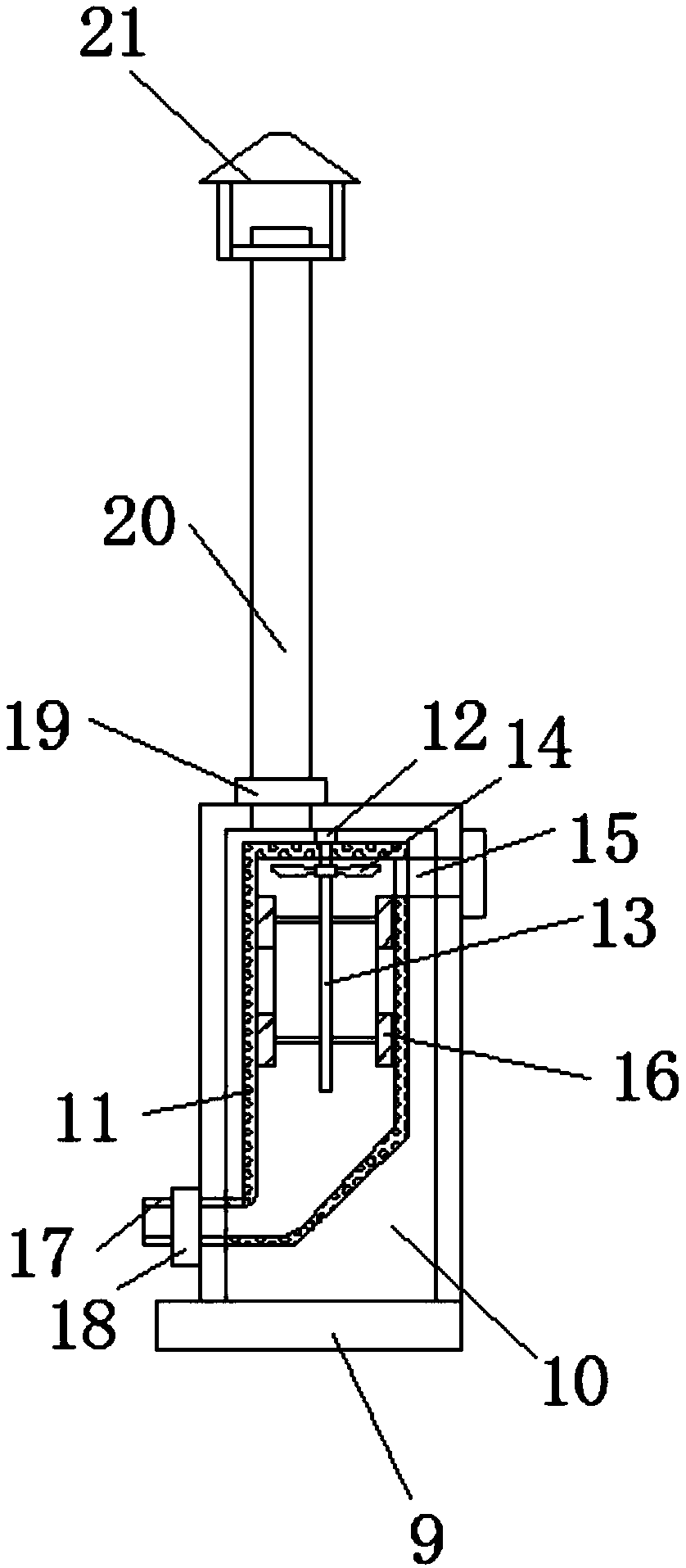
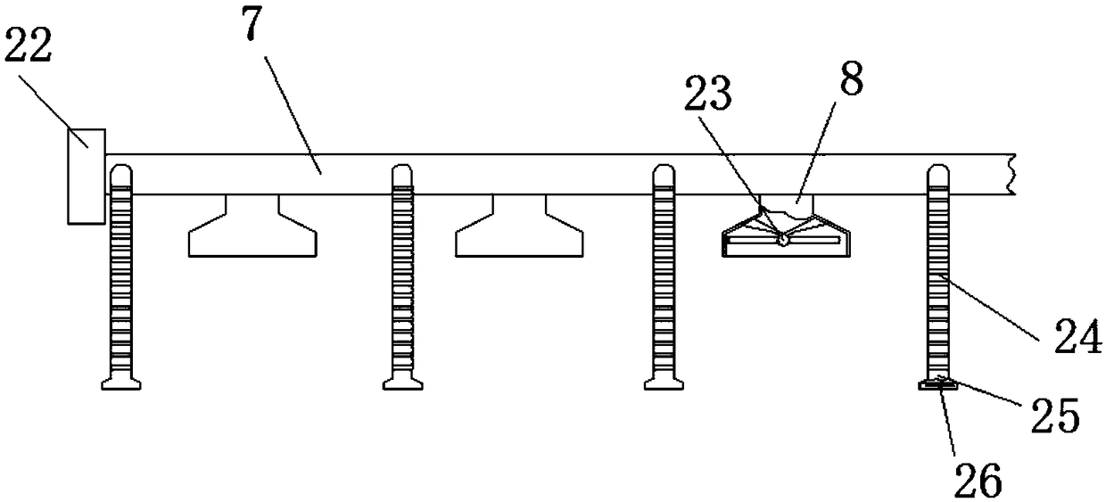
[0025] Embodiment one: refer to Figure 1-4 , a kind of replacement ventilation and dust removal equipment for a factory building, comprising a factory building body 1, a blower 3 is symmetrically fixed on the outer walls of both sides of the factory building body 1 through a first fixing seat 2, and the blower 3 is connected to an exhaust hood 5 through an air pipe 4, and The air pipe 4 runs through the plant body 1, the exhaust hood 5 is located inside the plant body 1, the top of the plant body 1 is welded with a beam 6, the beam 6 is fixed with an exhaust pipe 7, and the exhaust pipe 7 is connected to the first suction pipe 7. Cover 8, a purifier 10 is fixed on the outer wall of one side of the plant body 1 through the second fixed seat 9, a filter cover 11 is clamped inside the purifier 10, a swivel seat 12 is fixed at the center of the top plate inside the purifier 10, and the swivel seat The top of 12 is fixed with a rotating shaft 13, and the rotating shaft 13 runs thr...

Embodiment 2

[0026] Embodiment two: refer to figure 1 and image 3 , the exhaust pipe 7 is conductively connected with the filter cover 11 inside the purifier 10 through the air intake pipe 15, and the second suction cover 25 is connected to the exhaust pipe 7 through a hose 24, and the inner bolts of the second suction cover 25 A second suction fan 26 is fixed, and a plurality of first suction hoods 8 are arranged in total, and a plurality of first suction hoods 8 are equidistantly arranged on the exhaust pipe 7, and the first suction hoods 8 are used for suctioning the factory building. The air in the body 1 is replaced by air. The second suction hood 25 can be fixed in the area where the dust gas is generated inside the plant body 1 through the stretching of the hose 24, and the generated dust gas can be directly discharged, which is beneficial to reduce Dust, improve indoor air quality.

Embodiment 3

[0027] Embodiment three: refer to Figure 1-2 , the top of the purifier 10 is connected with an exhaust pipe 20, a waterproof cover 21 is fixed at the top opening of the exhaust pipe 20, and a second control valve 19 is fixed on the exhaust pipe 20, and the second control valve 19 is used to control the exhaust The conduction and closing of the pipe 20, the waterproof cover 21 is used to place the exhaust pipe 20 to enter water and improve its waterproof ability.


PUM


Abstract

The invention discloses displacement ventilation dusting equipment used for a workshop. The displacement ventilation dusting equipment comprises a workshop body; air supplying fans are symmetrically fixed on two side outer walls of the workshop body through first fixing bases; each air supplying fan is connected with an exhaust shield through an air conveying pipe; the air conveying pipes penetrate through the workshop body; and the exhaust shields are located in the workshop body. In the displacement ventilation dusting equipment, a purifier is arranged, so that air displaced by the displacement ventilation dusting equipment used for the workshop is exhausted after being purified by the purifier; the environment is protected; a rotary shaft is arranged at the central part in the purifier,the air exhausted through an air inlet pipe is in contact with a driving fan on the rotary shaft; the rotary shaft is driven to rotate by the driving fan, so that a cleaning brush on the rotary shaftcan automatically clean a filter shield in the purifier; and besides, the top part of the filter shield is connected with a slag discharging pipe which penetrates through the purifier; and filteringslags in the filter shield can be automatically cleaned by opening the slag discharging pipe; and therefore, cleaning of the purifier is very convenient and rapid, and self-cleaning is realized.

Description

technical field [0001] The invention relates to the technical field of ventilation equipment, in particular to a replacement ventilation and dust removal equipment for a factory building. Background technique [0002] Ventilation, also known as ventilation, is to send enough fresh air into the indoor space by mechanical or natural methods, and at the same time discharge the dirty air that does not meet the hygienic requirements, so that the indoor air can meet the hygienic requirements and the needs of the production process. The various facilities that complete the ventilation work in the building are collectively referred to as ventilation equipment. Ventilation is divided into natural ventilation and mechanical ventilation according to the power that the air flow relies on. Mechanical ventilation uses fans as the power to cause air flow. Mechanical ventilation is not limited by natural conditions. Air supply and exhaust can be carried out according to needs to obtain a st...

Claims


Application Information

Patent Timeline
IPC IPC(8): F24F7/007F24F3/16F24F13/28
CPCF24F7/007F24F13/28F24F8/10F24F8/108
Inventor 马勇
Owner 马勇
Why Eureka
Try Eureka