Method for forming an air gap between metal wiring lines and a metal wiring structure

A metal connection and air gap technology, which is applied in the direction of electrical components, electric solid devices, circuits, etc., can solve the problems of short circuit of metal connection, short circuit of metal connection with small spacing, influence on the structure and shape of the side wall of metal connection, etc. , to avoid short circuits, overcome cracks, and achieve good uniformity

Active Publication Date: 2018-11-13
SHANGHAI HUAHONG GRACE SEMICON MFG CORP
View PDF3 Cites 2 Cited by
  • Summary
  • Abstract
  • Description
  • Claims
  • Application Information

AI Technical Summary

Problems solved by technology

However, when the process node is below 0.20 microns, such as 0.13 microns, when the metal wiring pitch is less than 0.25 microns, the thickness of the SRO and FSG at the sidewall of the metal wiring is thinner, especially at the position where the bottom edge of the metal wiring is insufficiently covered, and There are still cracks in the corner edge profile of the side wall of the metal connection, such as figure 2 The narrow and long slit-like lines at the junction of the hollow air gap and the corner edge of the side wall of the metal connection are cracks, please refer to Figure 2 to Figure 4 , the crack will cause the fluorine (F) in the FSG to penetrate along the crack to the vicinity of the metal connection aluminum, and then contact with the aluminum (Al) to undergo a chemical reaction, causing the reaction product 70 of Al and F to flow into the air gap 60, This results in a short circuit between the metal wires on both sides of the air gap
That is to say, in the process below 0.20 microns, the critical dimension of the metal wiring becomes smaller, and the space between the metal wiring also becomes smaller. When SRO and FSG are used as trench filling materials, not only The filling effect of the silicon dioxide covered by the sidewall of the small-pitch metal wiring is not good, which affects the morphology of the sidewall structure of the metal wiring, and also causes a short circuit between the small-pitch metal wiring

Method used


Image

  • Method for forming an air gap between metal wiring lines and a metal wiring structure
  • Method for forming an air gap between metal wiring lines and a metal wiring structure
  • Method for forming an air gap between metal wiring lines and a metal wiring structure

Examples


Embodiment Construction

[0033] The present invention is described in detail below in conjunction with accompanying drawing:

[0034] An embodiment of the present invention provides a method for forming an air gap between metal wirings, including the following steps:

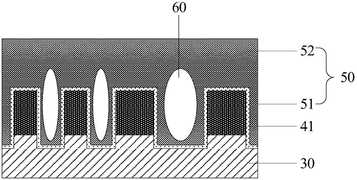
[0035] Step 101, please refer to Figure 5 , an inter-metal dielectric layer 300 is provided, and the material of the inter-metal dielectric layer 300 is an alternative material such as silicon dioxide. Among them, the inter-metal dielectric layer can be the dielectric layer under the bottom metal layer, which is called an inter-layer dielectric layer (Inter Layer Dielectric, ILD), or it can be the dielectric layer under the top and middle metal layers, called an inter-metal layer. Medium layer (Inter Metal Dielectric, IMD).

[0036] Step 102, please refer to Figure 5 , forming a metal layer (Metal) 400 on the inter-metal dielectric layer 300; the metal layer 400 is aluminum.

[0037] Step 103, please refer to Figure 6 and Figu...


PUM


Abstract

The invention provides a method for forming an air gap between metal wiring lines and a metal wiring structure. The method comprises the following steps: providing a metal interlayer dielectric layer;forming a metal layer on the interlayer dielectric layer; etching the metal layer to form a plurality of metal lines spaced apart from each other; a metal interlay dielectric layer is etched to forma trench, the depth of the trench is smaller than the thickness of the metal interlayer dielectric layer, a metal layer is sequentially covered with a silicon-rich oxide, a plasma-enhanced tetraethylorthosilicate and fluorine-doped silica or a plasma-enhanced tetraethylorthosilicate and non-fluorine-doped silica to form an interconnected dielectric lay and an air gap between the metal lines. The invention can improve the filling appearance of the side wall of the metal connection and avoid the short circuit phenomenon between the metal connections.

Description

technical field [0001] The invention relates to the technical field of semiconductor manufacturing, in particular to a method for forming an air gap between metal wirings and a metal wiring structure. Background technique [0002] In the technical field of manufacturing semiconductor devices, the parasitic capacitance between metal wirings is not only determined by the metal spacing, metal thickness and wiring width, but also affected by the dielectric constant of the medium between the metal wirings. The dielectric material filled after the metal etch is usually silicon dioxide with a dielectric constant between 3.2-4.0. With the advancement of process nodes, the line width and spacing of metal connections are getting smaller and smaller, and the parasitic capacitance between metal connections is also increasing, and the impact on circuit performance is also increasing. However, the thickness of the metal wires and the minimum distance between the wires are limited by the ...

Claims


Application Information

Patent Timeline
Patent Type & Authority Applications(China)
IPC IPC(8): H01L23/522H01L23/528H01L21/768
CPCH01L21/768H01L23/5222H01L23/528
Inventor 孙玉红吴建荣
Owner SHANGHAI HUAHONG GRACE SEMICON MFG CORP
Why Eureka
Try Eureka