Motor rotor and a brushless motor applying the same

A technology of motor rotor and brushless motor, which is applied in the direction of electrical components, electromechanical devices, electric components, etc., can solve the problems of low cost of permanent magnets, large torque ripple, etc., and achieve material saving, stable torque output, and easy assembly Effect

Inactive Publication Date: 2018-11-13
GUANGDONG JINBA INTELLIGENT TECHNOLOGY CO LTD
View PDF3 Cites 2 Cited by
  • Summary
  • Abstract
  • Description
  • Claims
  • Application Information

AI Technical Summary

Problems solved by technology

The permanent magnet of this shape is low in cost, but the disadvantage of the plug-in type is that the torque ripple is large

Method used


Image

  • Motor rotor and a brushless motor applying the same
  • Motor rotor and a brushless motor applying the same
  • Motor rotor and a brushless motor applying the same

Examples


Embodiment Construction

[0020] The present invention will be further described below in conjunction with the accompanying drawings and embodiments.

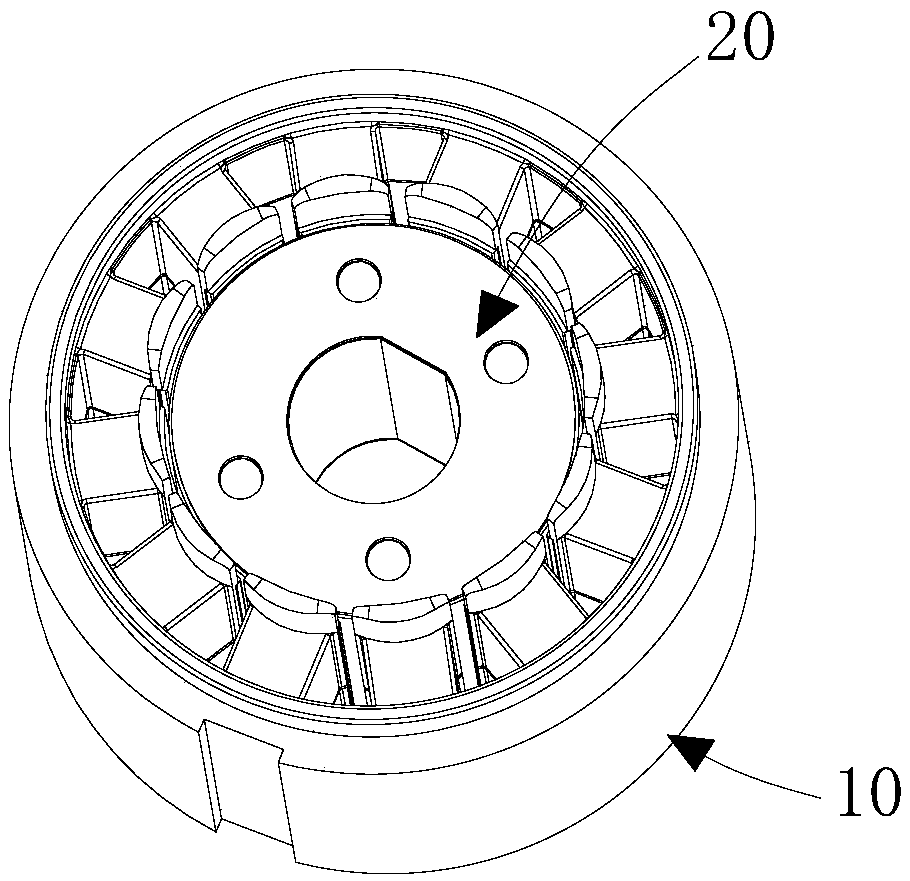
[0021] refer to figure 1 , a brushless motor provided by the present invention, the brushless motor is especially suitable for a compressor of an electric vehicle. The brushless motor includes a motor stator 10 and a motor rotor 20 installed in the motor stator 10 . Because the main improvement of the present invention is in motor rotor 20, so figure 1 The structure of the motor is shown simplified.

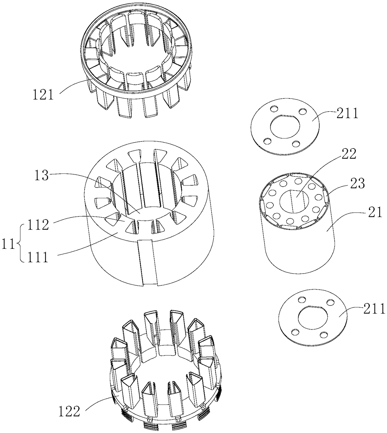
[0022] refer to figure 2 The motor stator 10 includes a stator core 11, a winding (not shown) wound to the stator core 11 and an insulating frame 121 installed on the two axial ends of the stator core 11 for insulating the stator core 11 and the winding , 122. The stator core 11 includes an annular yoke portion 111 and a plurality of stator teeth 112 protruding inward from the yoke portion 111 , and the above-mentioned windings are wound on the plura...


PUM


Abstract

The invention relates to a motor rotor and a brushless motor applying the same. The motor rotor comprises a rotor core and a plurality of permanent magnets, wherein an axial mounting hole for fixedlymounting the rotor core to a motor rotating shaft is formed in the center of the rotor core, and the plurality of permanent magnets are embedded in the rotor core at intervals in the circumferential direction of the rotor core; each permanent magnet is provided with a radial inner side surface and a radial outer side surface, the radial inner side surface is a plane, and the radial outer side surface is an arc surface; the radial thickness of each permanent magnet gradually decreases from the circumferential center to two circumferential ends. Torque fluctuation of the motor can be reduced, and the motor rotor core is easy to assemble, saves materials and has low cost.

Description

【Technical field】 [0001] The invention relates to the technical field of motors, in particular to a motor rotor and a brushless motor using the motor rotor. 【Background technique】 [0002] The rotor of a brushless motor consists of a rotor core and several permanent magnets. There are two types of installation methods for permanent magnets: surface mount type and plug-in type. The surface-mounted type refers to affixing several arc-shaped permanent magnets to the outer peripheral surface of the cylindrical rotor core, and using a cylindrical protective magnetic ring to enclose the several arc-shaped permanent magnets. The disadvantage of the surface mount type is that there is a lot of waste of arc-shaped permanent magnet material, and the assembly cost is high. The insertion type refers to inserting a flat permanent magnet into the rotor core along the axial direction of the rotor. The permanent magnet of this shape is low in cost, but the disadvantage of the plug-in typ...

Claims


Application Information

Patent Timeline
Patent Type & Authority Applications(China)
IPC IPC(8): H02K1/27
CPCH02K1/2766
Inventor 林楚辉
Owner GUANGDONG JINBA INTELLIGENT TECHNOLOGY CO LTD
Why Eureka
Try Eureka