Composite magnetic pole type surface-mounted permanent magnet synchronous motor

A technology for permanent magnet synchronous motors and combined magnetic poles, which is applied to synchronous machines, synchronous motors with stationary armatures and rotating magnets, magnetic circuit shape/style/structure, etc., and can solve harmonics, irreversible demagnetization, and motor performance degradation and other problems, to achieve the effect of reducing stator iron loss and torque fluctuation, reducing anti-demagnetization ability and improving reliability

Active Publication Date: 2016-03-30
HARBIN INST OF TECH
View PDF6 Cites 13 Cited by
  • Summary
  • Abstract
  • Description
  • Claims
  • Application Information

AI Technical Summary

Problems solved by technology

[0004] The purpose of the present invention is to solve the problems of harmonics and partial irreversible demagnetization in the air-gap magnetic field of rare earth permanent magnet synchronous motors driven by sine waves, especially at high temperatures, the irreversible demagnetization of permanent magnet materials will lead to the decline of motor performance , providing a combined magnetic pole surface mount permanent magnet synchronous motor

Method used


Image

  • Composite magnetic pole type surface-mounted permanent magnet synchronous motor
  • Composite magnetic pole type surface-mounted permanent magnet synchronous motor
  • Composite magnetic pole type surface-mounted permanent magnet synchronous motor

Examples


specific Embodiment approach 1

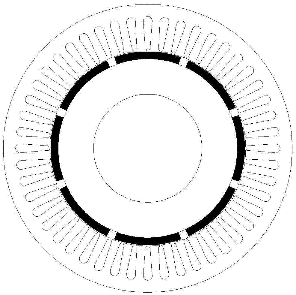
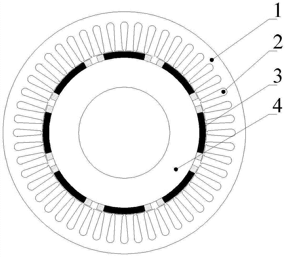
[0012] Specific implementation mode one: the following combination Figure 2 to Figure 4 This embodiment is described. The combined magnetic pole surface-mounted permanent magnet synchronous motor described in this embodiment includes a rotor and a stator. The rotor is arranged inside the stator. A radial air gap is left between the rotor and the stator. The stator includes a stator core 1 and a The stator winding 2 is arranged in the inner stator slot of the stator core 1; the rotor includes a plurality of rotor poles 3 and a rotor core 4, and the outer circular surface of the rotor core 4 is uniformly provided with a plurality of rotor poles 3;

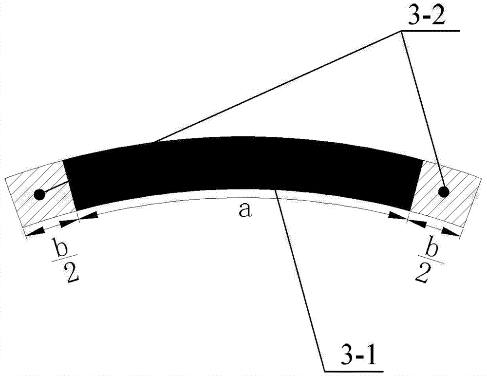
[0013] The rotor pole 3 includes a rare earth permanent magnet pole 3-1 and two ferrite permanent magnet poles 3-2; the two left and right end faces of the rare earth permanent magnet pole 3-1 are respectively provided with a ferrite permanent magnet pole 3-2, and the rare earth The permanent magnet pole 3-1 and the two ferrite perm...

specific Embodiment approach 2

[0017] Specific embodiment two: this embodiment further explains embodiment one, the arc length of the rare earth permanent magnet pole 3-1 is a, and the arc length of the ferrite permanent magnet pole 3-2 is b / 2, both of which meet the following conditions :

[0018] a ( Br 2 ) 2 + b ( Br 1 ) 2 c - 2 π { 2 ...


PUM


Abstract

The invention discloses a composite magnetic pole type surface-mounted permanent magnet synchronous motor, which belongs to the field of permanent magnet motors. The composite magnetic pole type surface-mounted permanent magnet synchronous motor aims to solve the problems that harmonic wave is in the presence in a sinusoidal-current-driven rare earth permanent magnet synchronous motor air gap magnetic field and local irreversible demagnetization always happen. The composite magnetic pole type surface-mounted permanent magnet synchronous motor comprises a rotor and a stator, wherein the rotor is arranged in the stator; a radial air gap is formed between the rotor and the stator; the excircle surface of the a rotor iron core is evenly provided with a plurality of rotor magnetic pols in a surface-mounted way; each rotor magnetic pole comprises a rare earth permanent magnetic pole and two ferrite permanent magnetic poles, wherein the left end surface and the right end surface of the rare earth permanent magnetic pole are independently provided with one ferrite permanent magnetic pole; the rare earth permanent magnetic pole and two ferrite permanent magnetic poles form a continuous circular-arc magnetic pole structure; and the magnetization directions of the rare earth permanent magnetic pole and two ferrite permanent magnetic poles are all radial magnetization and are the same. The permanent magnet synchronous motor of the structure causes the harmonic content of the air gap magnetic field to be lowered, motor efficiency is improved, the ferrite permanent magnet material is low in price, and cost is lowered.

Description

technical field [0001] The invention relates to a combined magnetic pole type rotor structure, which belongs to the field of permanent magnet motors. Background technique [0002] With the increasingly serious problems of the environment and energy crisis, high-efficiency and energy-saving electrical equipment has become a development trend, which greatly promotes the development of high-power-density, high-efficiency rare earth permanent magnet synchronous motors. However, the price of rare earth permanent magnet materials has remained high, and rare earth permanent magnet motors are greatly affected by price fluctuations of rare earth permanent magnet materials, so the cost of rare earth permanent magnet motors is also affected. The development space of magnetic synchronous motor. Moreover, rare earth materials are non-renewable resources, and excessive use of rare earth materials in motor systems will also cause damage to the environment. Therefore, under the premise of...

Claims


Application Information

Patent Timeline
Patent Type & Authority Applications(China)
IPC IPC(8): H02K21/14H02K1/27
CPCH02K1/2733H02K21/145
Inventor 郑萍程路明王伟男刘家琦赵白鸽
Owner HARBIN INST OF TECH
Why Eureka
Try Eureka