Permanent magnet power device

A technology of power devices and permanent magnets, applied in electromechanical devices, electrical components, etc.

Inactive Publication Date: 2018-11-13
朱伟
View PDF0 Cites 0 Cited by
  • Summary
  • Abstract
  • Description
  • Claims
  • Application Information

AI Technical Summary

Problems solved by technology

Due to the above-mentioned reasons, the application of permanent magnets on the power unit is still relatively elementary and needs to be improved urgently. Therefore, it is necessary to develop a kind of power unit based on permanent magnets.

Method used


Image

  • Permanent magnet power device
  • Permanent magnet power device
  • Permanent magnet power device

Examples


Embodiment 1

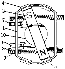
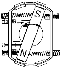
[0022] Figure 1-2 The permanent magnet power device shown includes a housing 1 made of non-magnetic material, a bar-shaped permanent magnet 2 in a vertical state that is rotatably installed in the housing 1 in the middle, four one ends are fixedly connected with the housing 1, The other end respectively pulls the springs 3 on both sides of the strip permanent magnet 2S pole and the strip permanent magnet 2N pole sides, and two upper magnetizers 4 installed on the upper end of the housing 1 and symmetrically located on both sides of the strip permanent magnet 2, Two lower magnetizers 5 installed on the lower end of the housing 1 and located symmetrically on both sides of the strip permanent magnet 2, the cylinder body is connected to the housing 1, the piston rod is connected to the two-way cylinder 6 at one end of the strip permanent magnet 2, and the installation On the housing 1, a travel switch 7 with a time-delay function is connected with the strip permanent magnet 2;

...

Embodiment 2

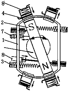
[0031] Figure 3-4 The permanent magnet power device shown also includes magnetic force air pumps 8 installed on the upper magnetic conductor 4 and the lower magnetic conductor 5 respectively. The rest are basically the same as in Embodiment 1, and one of the ways of doing work, that is, the output of air pressure, is realized by a magnetic air pump. Obviously other means can also be used, such as magnetically driven cranks or connecting rods.

[0032] It works like this:

[0033] When the bar-shaped permanent magnet attracts the magnetizer, there are two situations; one is that when the two poles of the bar-shaped permanent magnet (SN) attract a magnetizer (the opposite upper magnetizer and the lower magnetizer), there will be an attractive force. Utilize the generated attractive force to compress the spring, and the spring stores the attractive force. The purpose of storing the attractive force is to separate the power reserve when the two poles of the permanent magnet (SN...


PUM


Abstract

The invention discloses a permanent magnet power device and aims to provide an energy-saving and environment-friendly permanent magnet power device. The permanent magnet power device comprises a casing made of a non-magnetic material, a strip-shaped permanent magnet in a vertical state, four springs, two upper magnetic conductors, two lower magnetic conductors, a two-way cylinder and a travel switch, wherein the middle of the strip-shaped permanent magnet is rotationally mounted in the casing, one end of each of the four springs is fixedly connected with the casing, the other ends pull two sides of an S pole of the strip-shaped permanent magnet and two sides of an N pole of the strip-shaped permanent magnet; the two upper magnetic conductors are mounted at the upper end of the casing and symmetrically located on two sides of the strip-shaped permanent magnet, the two lower magnetic conductors are mounted at the lower end of the casing and symmetrically located on two sides of the strip-shaped permanent magnet, a cylinder body of the two-way cylinder is connected with the casing, and a piston rod is connected with one end of the strip-shaped permanent magnet; the travel switch is mounted on the casing, is connected with the strip-shaped permanent magnet and has a time delay function; the strip-shaped permanent magnet is close to adjacent end surfaces of the upper magnetic conductors and the lower magnetic conductors. The permanent magnet power device is applicable to multiple kinds of equipment requiring power drive.

Description

technical field [0001] The invention relates to the technical field of power equipment, in particular to a permanent magnet power device. Background technique [0002] As we all know, a permanent magnet is a very special functional material. It not only has permanent magnetism, but also has two poles, S and N, and can attract materials such as iron, nickel, and cobalt. However, materials such as copper, aluminum, and tin are also Can not attract, these are the unique functions of permanent magnets. Especially in recent years, with the development of science and technology, the energy density of permanent magnet materials has been greatly improved. Despite the above characteristics and advantages, people's knowledge and understanding of permanent magnets is still obviously insufficient. Firstly, it is believed that permanent magnets can only be used in the form of a static magnetic field. Secondly, permanent magnets can only operate with external power in terms of power mac...

Claims


Application Information

Patent Timeline
IPC IPC(8): H02K53/00
CPCH02K53/00
Inventor 朱伟
Owner 朱伟
Why Eureka
Try Eureka