A method of saving material in the process of spin-coating impellers

A material-saving and spin-coating technology, which is applied to the device and coating of the surface coating liquid, can solve the problems of material waste, achieve the effect of reducing pouring and saving coating materials

Active Publication Date: 2020-06-26
JILIN UNIV
View PDF5 Cites 0 Cited by
  • Summary
  • Abstract
  • Description
  • Claims
  • Application Information

AI Technical Summary

Problems solved by technology

Since the material must be fully filled and flowed into the interior every time it is poured, there is bound to be a part of excess material wasted. When the size of the impeller is large, the material used to pour the inner space of the runner will also increase, which will cause material loss. a lot of waste

Method used


Image

  • A method of saving material in the process of spin-coating impellers
  • A method of saving material in the process of spin-coating impellers
  • A method of saving material in the process of spin-coating impellers

Examples


Embodiment Construction

[0020] The steps of the present invention are as follows:

[0021] 1. Make filler blocks according to the flow channel of the impeller:

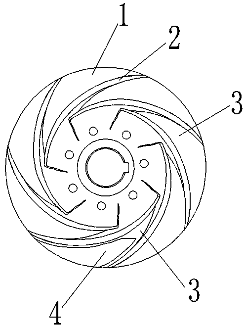
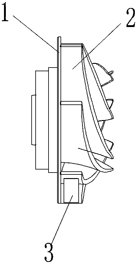
[0022] Such as figure 1 and figure 2 As shown, the impeller has a lower cover plate 1, an upper cover plate and several blades 2, and a flow channel 3 is formed between the lower cover plate 1, the upper cover plate and two adjacent blades 2, according to the shape of the inner space of the flow channel 3 The filler block 4 is made according to the shape, and there is a gap 5 between the peripheral side of the filler block 4 and the inner wall of the flow channel 3 .

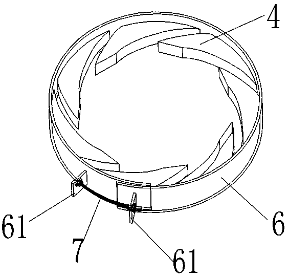
[0023] 2. Make a flexible ferrule and fix the filling block on the ferrule:

[0024] 2.1) First make the flexible metal hoop 6, weld two positioning buckles 61 to the two ends of the flexible metal hoop 6 respectively by electric welding, install and install the positioning bolt 7, as image 3 shown;

[0025] 2.2) Fix the filling block 4 evenly on the inner side of the f...


PUM


Abstract

The invention discloses a method for saving materials in the rotatable impeller coating process. The method comprises the steps that filler blocks are inserted into flow channels from a water inlet ofan impeller, the filler blocks occupy part of flow channel inner cavities so as to reduce coating material pouring, and then the purpose of saving the materials is achieved.

Description

technical field [0001] The invention belongs to the field of pump production and manufacturing, and particularly relates to a method for coating polymer materials on the flow-through part of a centrifugal pump impeller. Background technique [0002] Water pumps are one of the most important energy-consuming equipment in the field of industry and agriculture in my country. According to statistics, the power consumption of water pumps accounts for about 20% of the total power generation in the country. It is imperative to improve the operating efficiency of water pumps, save energy and reduce consumption. Since most types of pumps are relatively mature machines, improving pump efficiency from a design perspective is very difficult. Therefore, it is necessary to improve the efficiency of the pump from a perspective other than structural design. Using bionic technology to coat impellers with organic polymer drag-reducing materials such as polyurethane and silicone rubber is a ...

Claims


Application Information

Patent Timeline
Patent Type & Authority Patents(China)
IPC IPC(8): B05C7/04B05C11/08B05C15/00
CPCB05C7/04B05C11/08B05C15/00
Inventor 田丽梅张吉祥姚广海商延赓
Owner JILIN UNIV
Why Eureka
Try Eureka