Multi-rotor unmanned helicopter

A multi-rotor unmanned and helicopter technology, applied in the field of unmanned aerial vehicles, can solve problems such as damage to the aerodynamic performance of the unmanned aerial vehicle, increase the weight of the body structure, and cannot effectively reduce the harm, and achieve the protection of safety, large air resistance, and harm reduction. Effect

Pending Publication Date: 2018-11-16
韩磊
View PDF10 Cites 4 Cited by
  • Summary
  • Abstract
  • Description
  • Claims
  • Application Information

AI Technical Summary

Problems solved by technology

However, these methods can only protect ground personnel and facilities from the damage of high-speed rotating rotors, and cannot effectively reduce the harm to the body equipment itself and ground personnel and facilities caused by the falling impact of the UAV body.
At the same time, the protective retaining ring and mesh grille increase the weight of the body structure, reduce the aerodynamic force of the rotor, and seriously damage the aerodynamic performance of the UAV.

Method used


Image

  • Multi-rotor unmanned helicopter
  • Multi-rotor unmanned helicopter
  • Multi-rotor unmanned helicopter

Examples


Embodiment 1

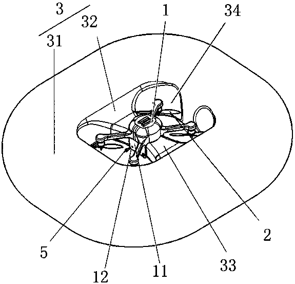
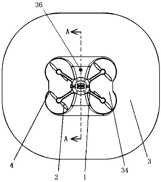
[0023] Such as Figure 1-3 As shown, a multi-rotor unmanned helicopter of the present invention includes a drone body 1, a propeller 2 and an air duct 3.

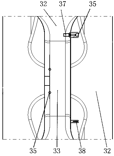
[0024] The inflatable duct 3 includes an annular airbag 31 ; the inside of the annular airbag 31 protrudes toward the middle to form a connecting section 32 , and the inside of the connecting section 32 communicates with the annular airbag 31 . There are at least two connecting sections 32 , and installation components 33 are fixed between all connecting sections 32 . The drone body 1 is installed between the connection sections 32 through the installation member 33 ; the connection section 32 and the installation member 33 divide the annular airbag 31 into several ducts 34 . There are at least two propellers 2, which are respectively installed under the end of the drone body 1; the propellers 2 are wrapped in ducts 34 respectively. The lowest end of the propeller 2 or the UAV body 1 is not lower than the lowest end of th...

Embodiment 2

[0031] Based on Embodiment 1, a small projection lens is installed inside the connecting section 32; the small projection lens faces the side wall of the inflatable duct, forms a projection on the side wall of the inflatable duct, plays videos and images, and is used for advertisements, events, flights, etc. information notice.

Embodiment 3

[0033]Based on Embodiment 1, a camera is installed at the bottom of the drone body 1 . When the unmanned aerial vehicle of the present invention is used for inspection and monitoring of intelligent storage and logistics warehouses, based on the indoor positioning system, the unmanned aerial vehicles will fly circularly according to the planned path, and the objects and stacking conditions of the high-altitude shelves in the storage warehouse will be tracked and monitored in real time through the camera. The barcode identification on the outer surface of the storage package can be scanned to realize real-time inventory and statistics of the storage items.


PUM


Abstract

The invention belongs to the technical field of drones, and particularly relates to a multi-rotor unmanned helicopter. The multi-rotor unmanned helicopter comprises an unmanned helicopter body, propellers and an air inflating duct. The unmanned helicopter body is installed in the air inflating duct through an installing component,, and the propellers are wrapped in the middle of the air inflatingduct. The air inflating duct has lift force which can offset part of gravity of the unmanned helicopter. Meanwhile, the air resistance of the air inflating duct is large, so that the falling speed ofthe unmanned helicopter is reduced. The unmanned helicopter body and the propellers are wrapped by the air inflating duct, the surface of the air inflating duct can deform due to load-bearing compression, a buffer effect is achieved, and therefore the safety of unmanned helicopter equipment and staff and facilities on the surface is protected. Damage, caused by falling and colliding of the unmanned helicopter body, to the unmanned helicopter body equipment and the staff and the facilities on the ground can be effectively relieved.

Description

technical field [0001] The invention belongs to the technical field of unmanned aerial vehicles, in particular to a multi-rotor unmanned helicopter. Background technique [0002] With the gradual maturity of multi-rotor unmanned helicopter technology, the application of multi-rotor UAVs in aerial photography, entertainment, logistics, industrial and agricultural production and other fields is becoming more and more extensive, but it hinders the battery life and control reliability of multi-rotor UAVs. Factors, accidents of products accidentally falling into bombers in actual use also occur from time to time, which greatly restricts their application in indoor environments and densely populated areas. [0003] Existing multi-rotor UAV products mostly use engineering plastic retaining rings or mesh grilles to wrap the rotors, so as to achieve limited protection. However, these methods can only protect ground personnel and facilities from the damage of high-speed rotating roto...

Claims


Application Information

Patent Timeline
Patent Type & Authority Applications(China)
IPC IPC(8): B64D45/00B64C27/08
CPCB64C27/08B64D45/00
Inventor 韩磊
Owner 韩磊
Why Eureka
Try Eureka