Cantilever crane of rigid rail

A cantilever crane and rigid technology, which is applied in portable hoisting devices, hoisting devices, cranes, etc., can solve problems such as difficulty in accessing ring chains, inconvenient operation, etc., and achieve the effects of reducing self-weight, reducing consumption, and reducing service life

Inactive Publication Date: 2018-11-16
HEFEI KIWI HEAVY MACHINERY CO LTD
View PDF0 Cites 0 Cited by
  • Summary
  • Abstract
  • Description
  • Claims
  • Application Information

AI Technical Summary

Problems solved by technology

However, the currently used cantilever cranes cannot control the rotation angle of the cantilever crane arbitrarily, and when the cantilever crane is at a high height from the ground, it is difficult for the operator to touch the lifting link chain, which makes the operation more inconvenient

Method used


Image

  • Cantilever crane of rigid rail
  • Cantilever crane of rigid rail
  • Cantilever crane of rigid rail

Examples


Embodiment 1

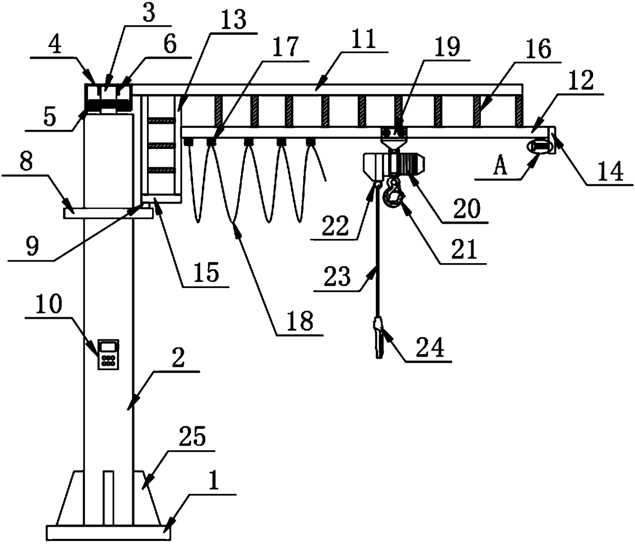
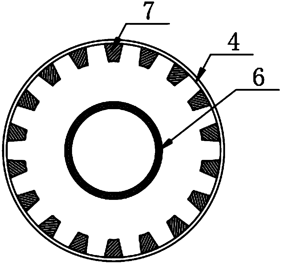
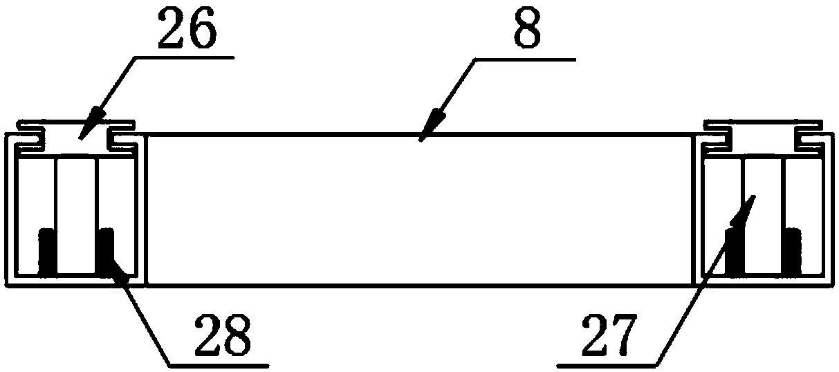
[0024] The present invention provides such as Figure 1-4 A rigid rail cantilever crane shown includes an installation base 1, a column 2 is vertically provided on the top of the installation base 1, and a first guide rod 3 is vertically provided on the top of the column 2, and the first guide rod 3 A first guide cylinder 4 is sheathed on the outside, a second guide cylinder 8 is sleeved on the column 2, a controller 10 is provided on the surface of the column 2, and a cross bar 11 is fixed on one side of the first guide cylinder 4 , the bottom of the cross bar 11 is provided with a guide rail 12, one end of the guide rail 12 is provided with a vertical bar assembly 13 and the other end is provided with a limiting plate 14, the bottom end of the vertical bar assembly 13 is provided with a connecting rod 15, the guide rail 12 A wire fixing clip 17 and an electric trolley 19 are arranged on the top, and a wire 18 is fixed on the wire fixing clip 17. The electric trolley 19 is ar...

Embodiment 2

[0030] Further, in the technical solution of Embodiment 1, the vertical rod assembly 13 is composed of two vertical rods arranged parallel to each other, and a reinforcing rod 16 is fixed between the two vertical rods, and the horizontal rod 11 and the guide rail 12 is also provided with reinforcement rods 16, the number of the number of reinforcement rods 16 is set multiple, can form a plurality of cavities between the two vertical rods and the cross rod 11 and the guide rail 12, so that while ensuring the strength of the cantilever crane itself At the same time, the consumption of materials is reduced, the production cost is saved, and the self-weight of the cantilever crane can be greatly reduced.

[0031] Further, in the technical solution of Example 1, the top of the installation base 1 is welded with a fixed plate 25, and the number of the fixed plates 25 is provided in multiples, and is evenly distributed on the surface of the column 2. The fixed plate 25 and the Weldin...


PUM


Abstract

The invention discloses a cantilever crane of a rigid rail. The cantilever crane of the rigid rail comprises an installing substrate. The top of the installing substrate is vertically provided with astand column. The top of the stand column is vertically provided with a first guiding rod. The exterior of the first guiding rod is sleeved with a first guiding cylinder. The stand column is sleeved with a second guiding cylinder. The surface of the stand column is provided with a controller. One side of the first guiding cylinder is fixedly provided with a cross rod. The bottom of the cross rod is provided with a guide rail. One end of the guide rail is provided with a vertical rod component and the other end is provided with a limiting plate. The bottom end of the vertical rod component is provided with a connecting rod. The cantilever crane of the rigid rail is capable of, through the cooperated use of the guiding rod, the guiding cylinders and a sleeve ring, enabling an operator to rotate the cantilever crane in 360 degrees through pulling a connecting rope, and convenient and rapid. Through the cooperated use of a buffer rubber cushion and a buffer spring, the double-layer buffereffect can be provided to a motor-driven carrier, the motor-driven carrier is prevented from colliding with the limiting plate because of an oversize moving speed, so that the motor-driven carrier isdamaged.

Description

technical field [0001] The invention relates to the field of cranes, in particular to a rigid rail cantilever crane. Background technique [0002] With the continuous development of the economy, cantilever cranes have been widely used in economic construction. However, the currently used cantilever cranes cannot control the rotation angle of the cantilever crane arbitrarily, and when the cantilever crane is at a high height from the ground, it is difficult for the operator to touch the ring chain, which makes the operation more inconvenient. [0003] Therefore, it is necessary to invent a kind of rigid rail cantilever crane to solve the above problems. Contents of the invention [0004] The purpose of the present invention is to provide a rigid rail cantilever crane. By using the guide rod, the guide cylinder and the collar together, the operator can realize the 360° rotation operation of the cantilever crane by pulling the connecting rope, which is convenient and quick. ...

Claims


Application Information

Patent Timeline
IPC IPC(8): B66C23/16B66C23/62B66D3/20B66D3/12
CPCB66C23/166B66C23/62B66D3/12B66D3/20
Inventor 杨孝先龚子运王金龙黄浩
Owner HEFEI KIWI HEAVY MACHINERY CO LTD
Why Eureka
Try Eureka