Dynamic compaction machine automatic lubricating system and control method thereof

A technology of automatic lubrication and dynamic compaction machine, applied in the direction of gear lubrication/cooling, mechanical equipment, transmission parts, etc., can solve the problems of high labor cost, difficulty in manual grease filling, time-consuming and labor-intensive grease filling work, etc. To achieve the effect of saving labor costs and efficient lubrication

Pending Publication Date: 2018-11-16
HANGCHA GRP
View PDF14 Cites 2 Cited by
  • Summary
  • Abstract
  • Description
  • Claims
  • Application Information

AI Technical Summary

Problems solved by technology

Because it is an open gear transmission, after manually applying grease, it can only be lubricated locally and for a short time. Although there is grease accumulation in the casing, the grease is basically absorbed on the inner wall of the casing, and only a small part of the bottom of the casing Grease is reused
[0004] The lubrication method of rolling bearings is usually manually greased with a grease gun. Due to the compact structure of the dynamic compaction machine, some lubrication points are located in a small space, so it is difficult to manually grease
In addition, the amount of grease injected and the interval between grease injections at each lubrication point are different, resulting in time-consuming and labor-intensive filling of grease and high labor costs

Method used


Image

  • Dynamic compaction machine automatic lubricating system and control method thereof
  • Dynamic compaction machine automatic lubricating system and control method thereof
  • Dynamic compaction machine automatic lubricating system and control method thereof

Examples


Embodiment Construction

[0034] For ease of understanding, the present invention will be further described below in conjunction with the accompanying drawings.

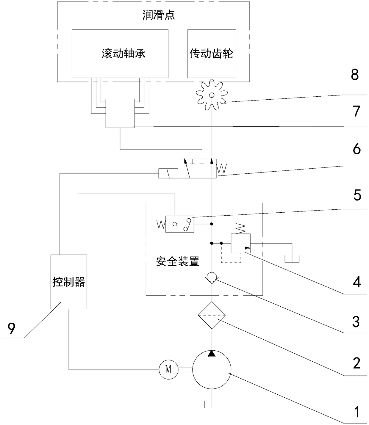
[0035] see figure 1 , is a schematic diagram of the principle of an automatic lubrication system for a dynamic tamping machine provided by an embodiment of the present invention. The automatic lubrication system for a dynamic tamping machine includes an electric lubrication pump 1, an electromagnetic reversing valve 6, a lubrication gear 8, a distributor 7 and a controller 9 .

[0036] Wherein, the controller 9 has a time setting unit and a timing unit, the electric lubricating pump 1 and the electromagnetic reversing valve 6 are electrically connected to the controller 9, and the inlet of the electromagnetic reversing valve 6 is connected to the outlet of the electric lubricating pump 1 through a pipeline .

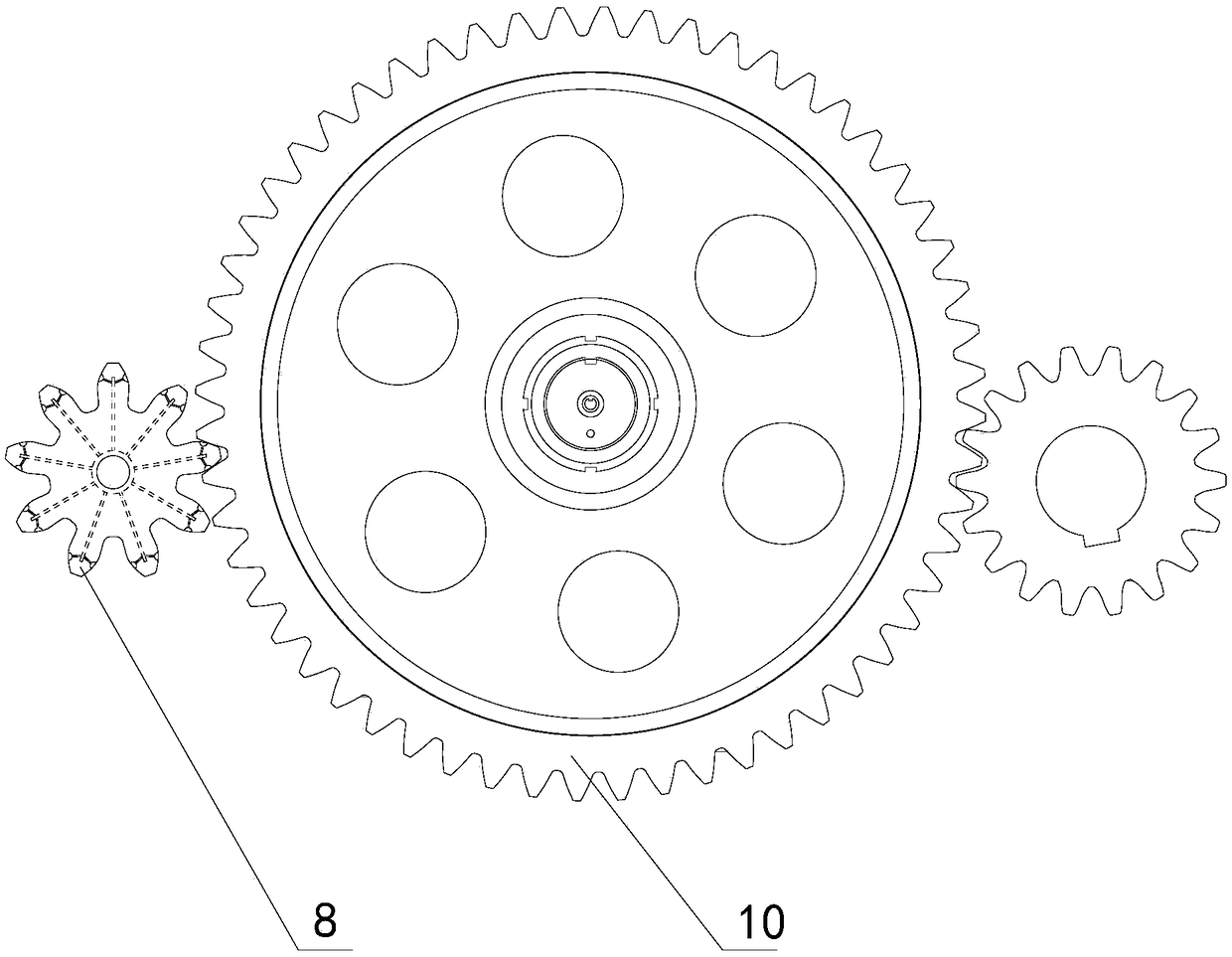
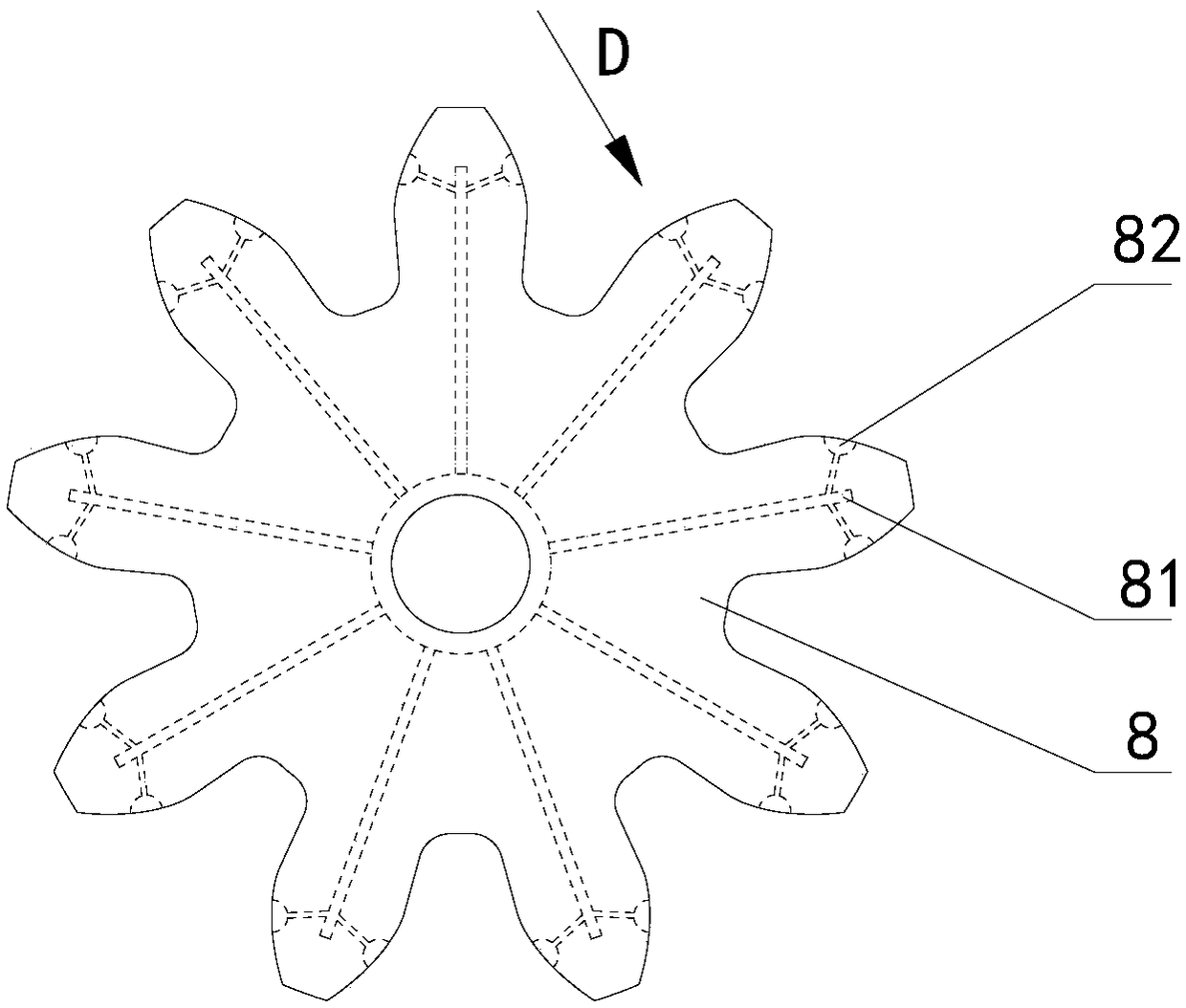
[0037] The lubricating gear 8 is used for the transmission gear 10 in the hoisting device of the dynamic compactor (see figure 2 )...


PUM


Abstract

The invention provides an automatic lubricating system and a control method of a dynamic compaction machine. The dynamic compaction machine automatic lubricating system comprises an electric lubricating pump (1), an electromagnetic exchange valve (6), a distributor (7), a lubricating gear (8) and a controller (9), and an inlet of the electromagnetic exchange valve (6) is connected with an outlet of the electric lubricating pump (1) through a pipeline; the interior of the lubricating gear (8) is provided with first oil channels (81) which are radiated from the center to each gear tooth, outletsof the first oil channels (81) are located on the tooth surface of the gear teeth, and inlets of the first oil channels (81) are connected with a first outlet of the electromagnetic exchange valve through pipelines; the interior of the distributor (7) is provided with one-inlet and multiple-outlet second oil channels, the inlet of the second oil channels is connected with a second outlet of the electromagnetic exchange valve (6) through a pipeline. According to the dynamic compaction machine automatic lubricating system, the transmission gear and rolling bearings of the dynamic compaction machine can be conveniently and effectively lubricated, time and labor are saved, and labor cost is saved.

Description

technical field [0001] The invention relates to the technical field of dynamic compaction machines, in particular to an automatic lubrication system of dynamic compaction machines and a control method thereof. Background technique [0002] The friction pairs that need to be lubricated on the dynamic compaction machine mainly include transmission gear and rolling bearing. The transmission gear refers to the meshing gear in the lifting device, and the rolling bearing mainly refers to the rolling bearing in the slewing device, luffing device and lifting device. [0003] At present, the lubrication method of transmission gears is usually to manually apply grease to the gears regularly. In order to improve the lubrication effect, a cover with grease accumulation function will be installed outside the gears. When the gears rotate, the deposited grease can be scraped up for lubrication. . Because it is an open gear transmission, after manually applying grease, it can only be lubri...

Claims


Application Information

Patent Timeline
Patent Type & Authority Applications(China)
IPC IPC(8): F16H57/04E02D3/046
CPCF16H57/0435F16H57/0441F16H57/0464F16H57/0467F16H57/0471E02D3/046
Inventor 包奇石彦军姚俊娟方佳泳葛蔚烽高敏
Owner HANGCHA GRP
Why Eureka
Try Eureka