Collimating mirror regulating base

A technology for adjusting a base and a collimating mirror, applied in the field of collimating mirrors, can solve the problems of insufficient precision and few adjustment directions and angles, and achieve the effect of high precision

Inactive Publication Date: 2018-11-16
WUXI JIANGSU WEIFENG PRINTING MACHINE
View PDF1 Cites 0 Cited by
  • Summary
  • Abstract
  • Description
  • Claims
  • Application Information

AI Technical Summary

Problems solved by technology

[0004] Although this splicing type collimating mirror adjustment device and method can effectively improve the adjustment efficiency and energy utilization rate of the unit collimating mirror, its accuracy is often not enough, and the adjustment direction angle is also less.

Method used


Image

  • Collimating mirror regulating base
  • Collimating mirror regulating base
  • Collimating mirror regulating base

Examples


Embodiment 1

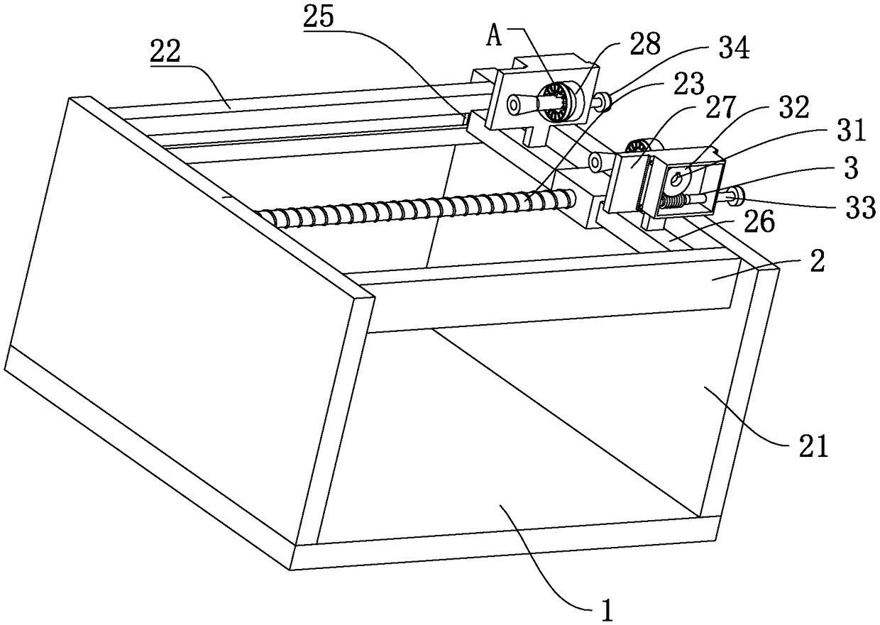
[0023] Embodiment 1: A kind of collimating mirror adjustment base, comprises support base 1, is also provided with adjusting device 2 on support base 1, and adjustment device 2 comprises the baffle plate 21 that is positioned at support base 1 both sides, between baffle plate 21 Two parallel chutes 22 are fixed on the baffle plate 21 at both ends, and a lead screw 23 parallel to the chute 22 is also provided between the chute 22, and one end of the lead screw 23 rotates with the side baffle plate 21 Connected, the other end of the lead screw 23 passes through the baffle 21 on the other side and is rotatably connected with the baffle 21 , and a rotating handle 24 is also provided on the top of the lead screw 23 outside the baffle 21 . At the same time, a support 26 is sheathed on the leading screw 23 , and both sides of the support 26 are provided with slide blocks 25 which can be effectively inserted into the chute 22 , and support rods 27 are also provided on both sides of the...


PUM


Abstract

The invention discloses a collimating mirror regulating base, and aims to provide a collimating mirror regulating base which can effectively adjust the position. According to the technical scheme, thecollimating mirror regulating base is characterized by comprising a supporting seat; a regulating device is further arranged on the supporting seat and comprises baffles located on both sides of thesupporting seat, two parallel-placed sliding grooves located between the baffles, a screw rod located between the sliding grooves, a rotating handle located outside the baffles and fixedly connected to the screw rod, a bracket arranged on the screw rod in a sleeving mode and with the two sides provided with sliding blocks used for being clamped into the sliding grooves, a supporting rod located onthe bracket, a bearing with the outer wall connected to the top end of the supporting rod, a dialing plate located on the outer wall of the bearing, blocking sheets located on the periphery of the inner wall of the sliding plate, a collimating mirror rotatably connected with bearing, and a rotating clamping plate located at the bottom of the collimating mirror and used for being clamped between the blocking sheets.

Description

technical field [0001] The invention relates to the field of collimating mirrors, in particular to a collimating mirror adjusting base. Background technique [0002] The collimating mirror is a collimating mirror for CO2 laser and infrared optical system, and the material is copper. In the prior art, lasers are generally equipped with corresponding collimating mirrors to overcome the above-mentioned shortcomings. The collimating mirror can change the diameter and divergence angle of the laser beam in the light adjustment system, so that the laser beam becomes a collimated parallel beam, so as to obtain a small high-power-density spot for use in different optical instruments and equipment. However, in practice During the application process, due to the influence of factors such as the processing error of the collimating mirror carrier, the error of the collimating mirror itself, and the assembly error between the collimating mirror and the collimating mirror carrier, the col...

Claims


Application Information

Patent Timeline
Patent Type & Authority Applications(China)
IPC IPC(8): F16M11/12
CPCF16M11/12
Inventor 吴伟平
Owner WUXI JIANGSU WEIFENG PRINTING MACHINE
Why Eureka
Try Eureka