
Operating trolley and its mechanical arm optical target positioning device and positioning method

A technology for positioning devices and robotic arms, applied in the direction of active optical measuring devices, measuring devices, measuring instruments, etc., can solve the problems of unsuitable positioning of the arm frame of the work trolley, achieve high reliability, high position resolution, and improve positioning The effect of precision

Active Publication Date: 2019-01-04
CHINA RAILWAY CONSTR HEAVY IND
View PDF1 Cites 0 Cited by
  • Summary
  • Abstract
  • Description
  • Claims
  • Application Information

AI Technical Summary

Problems solved by technology

The arm frame of the trolley involves many unfavorable factors such as variable cross-section, contact, and clearance, and the method of direct calibration through the whole is not suitable for the positioning of the arm frame of the operating trolley

Method used


Image

  • Operating trolley and its mechanical arm optical target positioning device and positioning method
  • Operating trolley and its mechanical arm optical target positioning device and positioning method
  • Operating trolley and its mechanical arm optical target positioning device and positioning method

Examples


Embodiment Construction

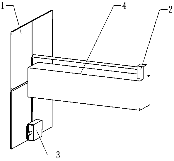
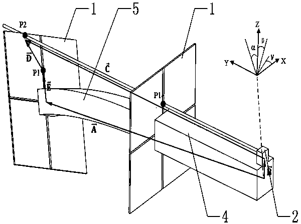
[0034] The core of the present invention is to provide an optical target positioning device for a work trolley and its mechanical arm, which can accurately obtain the dynamic coordinate position and posture information of the mechanical arm through the vector synthesis rule and improve the positioning accuracy. Another core of the present invention is to provide a positioning method using the above device.

[0035] In order to enable those skilled in the art to better understand the solution of the present invention, the present invention will be further described in detail below in conjunction with the accompanying drawings and specific embodiments.

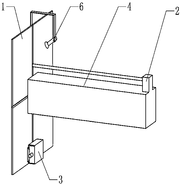
[0036] Please refer to Figure 1 to Figure 3 , figure 1 It is a structural schematic diagram of a specific embodiment of the optical target positioning device for the manipulator provided by the present invention; figure 2 It is a structural schematic diagram of another specific embodiment of the optical target positioning de...


PUM


Abstract

A robotic arm optical target positioning device, comprising a target (1) mounted at the tail end of a boom (5) of a robotic arm and perpendicular to an extending direction of the tail end of the boom, two-dimensional coordinate information of a light spot on the target being able to be acquired; an inclination sensor (3) mounted to the target and used for measuring an inclination attitude of the target; an optical rangefinder (2) capable of projecting a collectable light spot on the target, and capable of obtaining a beam length between the optical rangefinder and the target; and a controller for obtaining dynamic coordinate pose information of the tail end of the boom. Further disclosed are a positioning method using the robotic arm optical target positioning device, and an operation trolley. The positioning device and method improve the positioning accuracy of an arm frame of a trolley, and reduce pose errors caused by deformation of the arm frame. By means of the optical target, the response speed is fast, the position resolution is high, the reliability is high, and the detection data is only related to the energy center of the light spot. The present invention can realize real-time automatic measurement, and does not need manual intervention in the measurement process.

Description

technical field [0001] The invention relates to the field of engineering machinery, in particular to an operation trolley and an optical target positioning device for a mechanical arm thereof. In addition, the present invention also relates to a positioning method using the above device. Background technique [0002] During the construction of tunnel engineering, in order to prevent the surrounding rock from deforming and breaking, it is usually necessary to reinforce the surrounding rock by erecting arches, installing anchor rods, hanging steel mesh, and spraying concrete. Take the tunnel arch multi-functional operation trolley as an example. This trolley is an automatic tunnel construction equipment integrating arch positioning, installation and welding. The core operating arm is a multi-degree-of-freedom series mechanism. It is the basic requirement of the work trolley to realize the predetermined position and attitude of the terminal working device by the joint pose, an...

Claims


Application Information

Patent Timeline
Patent Type & Authority Patents(China)
IPC IPC(8): G01C15/00
CPCG01C15/002G01C15/008
Inventor 刘飞香郑大桥秦念稳夏毅敏韩奉林何锐波曾苗筠孙敏亮杨肖覃宗柱
Owner CHINA RAILWAY CONSTR HEAVY IND
Learn More