Supercharge Your Innovation With Domain-Expert AI Agents!

Illuminance testing system, method and device

A test system and illuminance technology, applied in photometry, optical radiation measurement, measuring devices, etc., can solve problems such as time-consuming, large random errors in measurement results, and cumbersome measurement processes, so as to improve accuracy, avoid damage, reduce The effect of time and cost

Inactive Publication Date: 2018-11-16
BOE TECH GRP CO LTD +1
View PDF5 Cites 2 Cited by
  • Summary
  • Abstract
  • Description
  • Claims
  • Application Information

AI Technical Summary

Problems solved by technology

[0004] However, the inventors have found that the following problems exist when using the above two methods to test the illuminance uniformity of the exposure surface: method 1 requires manual adjustment of the position of the illuminometer probe for many times, making the measurement process cumbersome and time-consuming. At the same time, the measurement value will change with the change of each point position, so that the random error of the measurement result is relatively large, resulting in low accuracy of the uniformity of illuminance on the exposed surface of the test; method 2: When multiple illuminance probes When there is an error in any one or more of them, it may cause greater errors in the test results of the illuminance uniformity of the exposure surface, thereby affecting the quality of the illuminance uniformity test of the exposure surface

Method used


Image

  • Illuminance testing system, method and device
  • Illuminance testing system, method and device
  • Illuminance testing system, method and device

Examples


Embodiment Construction

[0042] Embodiments of the present invention are described in detail below, examples of which are shown in the drawings, wherein the same or similar reference numerals designate the same or similar elements or elements having the same or similar functions throughout. The embodiments described below by referring to the figures are exemplary and are intended to explain the present invention and should not be construed as limiting the present invention.

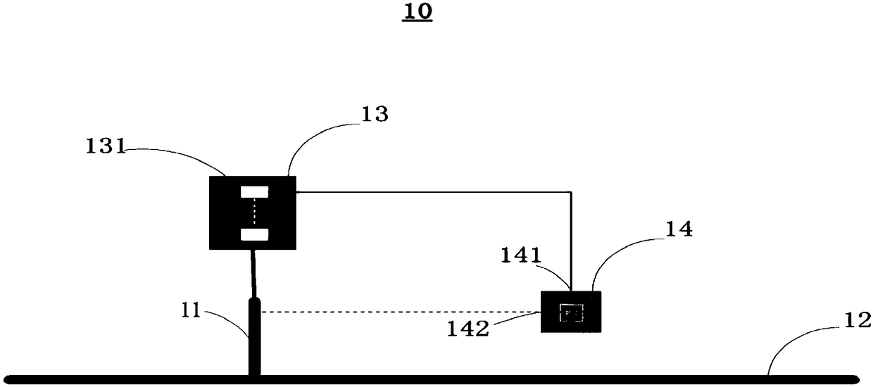
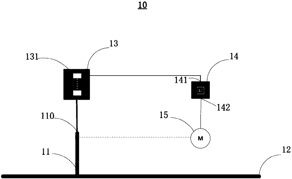
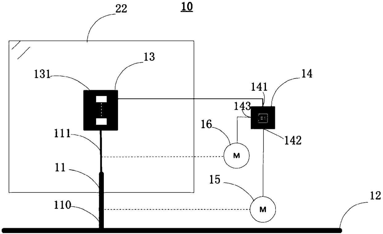
[0043] The present invention is mainly aimed at the prior art, when using an illuminometer probe to test the illuminance uniformity of the exposure surface, it is necessary to manually adjust the position of the illuminometer probe multiple times, which makes the measurement process more cumbersome and time-consuming. The measured value will also change with the change of the position of each point, which makes the random error of the measurement result relatively large, resulting in low accuracy of the uniformity of illumination ...


PUM


Abstract

The invention proposes an illuminance testing system, method and device, and the system comprises a first guide rail and a second guide rail, which are perpendicular to each other, an illuminance probe, and a controller, wherein the first guide rail and the second guide rail are perpendicular to each other. The illuminance probe comprises N illuminance sensors, wherein N is a positive integer which is greater than or equal to one. The illuminance probe is fixedly disposed at one end of the first guide rail. The other end of the first guide rail is movably connected with the second guide rail.The input end of the controller is connected with the output end of the illuminance sensor to obtain an illuminance value collected by the illuminance sensor. The first output end of the controller isconnected with the control end of the first guide rail to control the first guide rail to make reciprocating motion in the direction of the second guide rail. The system achieves the testing of the illuminance of an exposure surface through the setting of the illuminance probe on the movable guide rail and the control of the movement of the guide rails, thereby reducing the time and cost in manual testing, improving the accuracy of the illuminance testing of the exposure surface, and preventing the ultraviolet light emitted by an illuminance lamp from damaging a human body.

Description

technical field [0001] The invention relates to the technical field of electronic equipment, in particular to an illumination testing system, method and equipment. Background technique [0002] Generally, exposure equipment uses focused electron beams to expose organic polymers (commonly known as electronic resists or photoresists). After being irradiated by electron beams, the physical and chemical properties of photoresists change. A well-dissolved or poorly soluble region is formed in the solvent, thereby forming a fine pattern on the resist. Among them, the uniformity of illuminance on the exposure surface is an important index to ensure the consistency of exposure on the exposure surface. Therefore, testing the uniformity of illuminance on the exposure surface has become an essential operation. In particular, after the exposure lamp in the exposure equipment is replaced, it is necessary to conduct an illuminance test on the exposure surface to adjust the illuminance di...

Claims


Application Information

Patent Timeline
Patent Type & Authority Applications(China)
IPC IPC(8): G01J1/42G01J1/04
Inventor 叶超常进隆清德杨泽荣傅昌余刘佳希吴催豪高斌
Owner BOE TECH GRP CO LTD
Features
  • R&D
  • Intellectual Property
  • Life Sciences
  • Materials
  • Tech Scout
  • Unparalleled Data Quality
  • Higher Quality Content
  • 60% Fewer Hallucinations
Learn More