
Bridge quality analysis system and method based on image analysis

A quality analysis and image analysis technology, which is applied in the analysis of materials, the use of sound waves/ultrasonic waves/infrasonic waves to analyze solids, and the use of sound waves/ultrasonic waves/infrasonic waves for material analysis. Traffic and other issues

Inactive Publication Date: 2018-11-16
SHIJIAZHUANG INST OF RAILWAY TECH
View PDF8 Cites 0 Cited by
  • Summary
  • Abstract
  • Description
  • Claims
  • Application Information

AI Technical Summary

Problems solved by technology

[0005] The traditional detection method is the method of artificial visual recognition. Usually, the search and shape of cracks are measured and recorded by investigators through microscopes. This method has the disadvantages of closed traffic, heavy detection workload, long detection time, high detection cost, and artificial detection results. Factors greatly affect the shortcomings. At the same time, the inspectors need to go deep into the area where the crack is located through the inspection vehicle or scaffolding, which also brings many unpredictable safety hazards to the inspection.
[0006] The wave dispersion equation is generally a binary transcendental equation about wavenumber and frequency. When solving the solution of the dispersion relation in the complex wavenumber domain, the equation becomes a more complex ternary transcendental equation, and the coefficients of the dispersion equation may contain complex numbers , so it is very difficult to solve this kind of problem, and generally only can solve the dispersion relation for very special and very simple cases, which is far from enough for the analysis of various acoustic wave sensors with different structures
[0007] In the prior art, the safety assessment of bridges mainly relies on the assessment of human factors, and the deviation is large

Method used


Image

  • Bridge quality analysis system and method based on image analysis
  • Bridge quality analysis system and method based on image analysis
  • Bridge quality analysis system and method based on image analysis

Examples


Embodiment Construction

[0129] In order to further understand the content, features and effects of the present invention, the following examples are given, and detailed descriptions are given below with reference to the accompanying drawings.

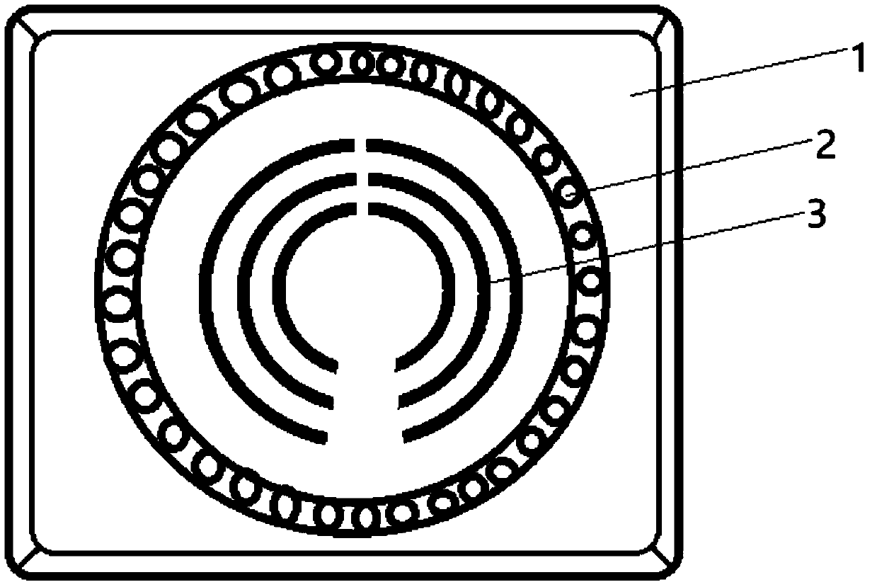
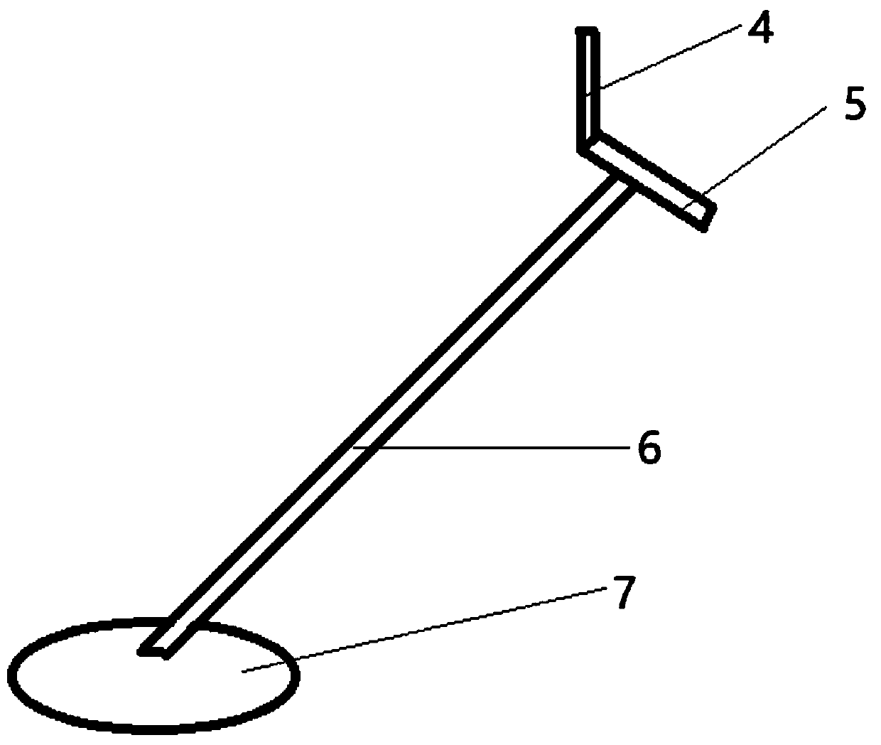
[0130] Such as figure 1 and figure 2 As shown, the bridge quality analysis system based on image analysis provided by the embodiment of the present invention is provided with an alarm and a sound wave detector, the alarm is provided with a housing 1, an LED light 2, and a bell 3, and the detector is provided with an operating Screen 4, handle 5, long rod 6, detection head 7. The bell 3 is embedded in the shell 1, the LED light 2 surrounds the bell 3 and is embedded in the shell 1, the upper end of the long rod 6 is connected to the handle 5 through a nut, and one end of the handle 5 is fixed by a nut Connected to the operation panel 4, the bottom of the long rod 6 is welded with a detection head 7.

[0131] The acoustic wave detector is externally connect...


PUM


Abstract

The invention belongs to the technical field of bridge diagnosis and discloses a bridge quality analysis system and method based on image analysis. The bridge quality analysis system based on image analysis comprises an alarm and an acoustic detector, wherein the alarm comprises a casing, LED lamps and a bell; the acoustic detector comprises an operation screen, a handle, a long pole and a detection head. The bell is embedded in the casing, the LED lamps surround the bell and are embedded in the casing, the upper end of the long pole is connected with the handle through a nut, one end of the handle is connected fixedly with the operation screen through a nut, and the detection head is welded at the bottom of the long pole. The bridge quality analysis system is simple in structure and convenient to operate, internal condition of a bridge can be detected precisely by the acoustic detector, the alarm can send warning timely when a quality problem occurs, information is supplied to an operator, bridge safety is guaranteed, and accidents are reduced greatly.

Description

technical field [0001] The invention belongs to the technical field of bridge diagnosis, and in particular relates to a bridge quality analysis system and method based on image analysis. Background technique [0002] At present, the existing technologies commonly used in the industry are as follows: [0003] At present, road traffic is the main artery of the national economy, and the road and bridge engineering structure is the throat of road traffic, which plays a vital role in ensuring the smoothness of the road. However, after the road and bridge are completed and opened to traffic, with the passage of time, various factors will reduce the safety of the road and bridge. For example, the original design does not meet the use requirements, the construction does not meet the design requirements, there are diseases in the road and bridge, and the materials are aging and corroded without timely maintenance. , the increase of vehicle load or the sharp increase of traffic volu...

Claims


Application Information

Patent Timeline
IPC IPC(8): G01N29/44G01N29/04
CPCG01N29/04G01N29/4472G01N2291/023G01N2291/0289
Inventor 李君君刘晓庆
Owner SHIJIAZHUANG INST OF RAILWAY TECH
Learn More