
An indoor test method for simulating the upward return of post-grouting grout at the pile tip

A test method and an indoor test technology are applied in the field of indoor test devices for simulating the upward return of grouting slurry at the pile end, which can solve the problems affecting the popularization and application of the post grouting technology at the pile end, the unreasonable size effect, and the study on the characteristics of mechanical properties. not deep enough

Active Publication Date: 2020-10-02
TONGJI UNIV
View PDF12 Cites 0 Cited by
  • Summary
  • Abstract
  • Description
  • Claims
  • Application Information

AI Technical Summary

Problems solved by technology

However, for the value of the return height of the grout, the value of the return height given in the "Technical Specifications for Building Pile Foundations" and the "Code for Design of Highway Bridge and Culvert Foundations and Foundations" is different, and a specific return height is generally given It is unreasonable not to consider factors such as grouting pressure, grouting amount, soil layer parameters, and pile size effects, and the research on the mechanical properties of the pile-soil contact surface in the upper return section of the grout is not deep enough, which will affect the pile tip. Popularization and Application of Grouting Technology

Method used


Image

  • An indoor test method for simulating the upward return of post-grouting grout at the pile tip
  • An indoor test method for simulating the upward return of post-grouting grout at the pile tip
  • An indoor test method for simulating the upward return of post-grouting grout at the pile tip

Examples


Embodiment

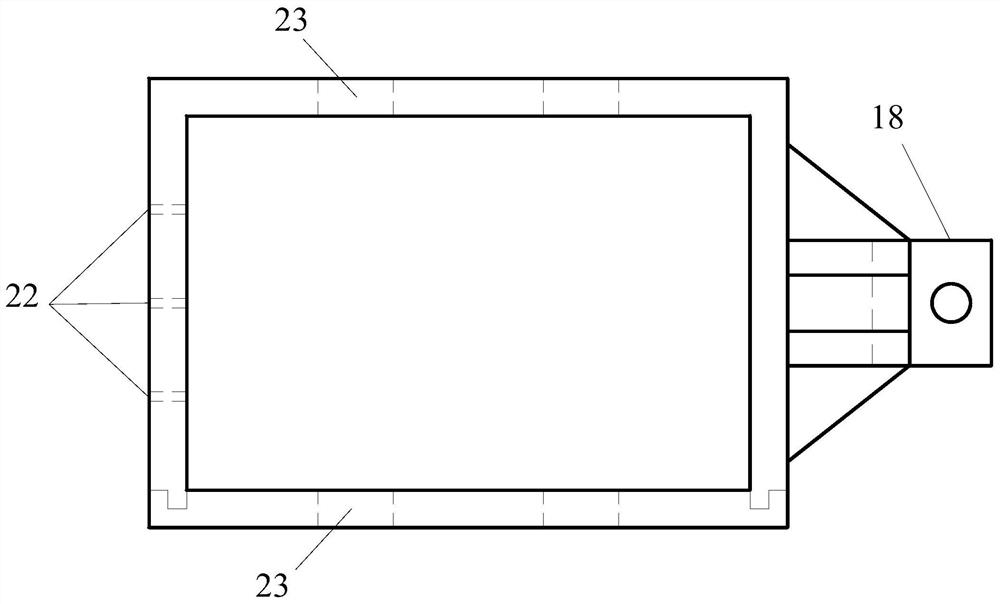
[0073] An indoor test device for simulating the upward return of grouting slurry after the pile tip, its connection structure is as follows figure 1 As shown, the device includes a test assembly and a grouting assembly, wherein the grouting assembly includes an air compressor 1, a slurry storage tank 9, etc., and the test assembly includes an interface shear instrument 17, an upper shear box 13, and a lower shear box 16 etc., the air compressor 1 is provided with a pressure gauge 2 and a first pressure regulating valve 3 . The top of the slurry storage tank 9 is provided with a flange top cover 8, and the top of the flange cover 8 is provided with a pressure relief valve 4, a slurry inlet 6 and a second pressure regulating valve 7, and the side wall of the slurry storage tank 9 is made of transparent plexiglass. , marked with a volume scale, the amount of slurry injection can be observed, the side of the bottom plate of the slurry storage tank 9 is provided with a slurry inlet...


PUM


Abstract

The invention relates to an indoor test device for simulating upward returning of post-grouting slurry and a test method thereof. The device comprises a test assembly and a grouting assembly, whereinthe grouting assembly includes an air compressor, a pressure-keeping slurry-storage tank, and the like, the test assembly includes an interface shearing device and a groutable shearing box composed ofan upper shearing box and a lower shearing box, a pressure-regulating valve, a pressure gauge and a slurry inlet are arranged at the top of the slurry-storage tank, and the bottom side of the slurry-storage tank is connected to a grouting pipeline of the upper shearing box through a grouting valve and a feed pipe, and the cement slurry is injected into a contact surface of soil and structure through the grouting pipeline of the upper shearing box. Compared with the prior art, the method can be used to simulate and research the influence of the on-site upward returning of the post-grouting slurry on a foundation pile bearing mechanism, by controlling the grouting pressure and the grouting amount, the grouting effects by the grouting pressure and the grouting amount can be studied, which ishelpful to reveal an upward returning mechanism of the post-grouting slurry, and the device provides reference for design and construction of the post-grouting slurry in practical pile engineering.

Description

technical field [0001] The invention relates to the technical field of post-pile grouting engineering, in particular to an indoor test device and a test method for simulating the upward return of post-pile grouting grout. Background technique [0002] With the continuous development of my country's engineering construction, pile foundations are widely used in housing construction, bridges, roads and other projects. However, due to the many and complex factors affecting the load-bearing characteristics of piles in the construction process, although scholars at home and abroad have conducted a lot of experimental and theoretical research on them, they have not yet had a unified understanding of the load-bearing mechanism. The current pile foundation design The parameter values ​​for the calculation of the bearing capacity of pile foundations in the code are still based on experience and lack theoretical support. During the construction of the pile foundation, especially the c...

Claims


Application Information

Patent Timeline
Patent Type & Authority Patents(China)
IPC IPC(8): G01N33/38
CPCG01N33/383
Inventor 赵春风吴悦赵程刘帆费逸王有宝
Owner TONGJI UNIV
Learn More