
A design method for dot distribution on the bottom surface of a side-entry light guide plate

A design method and technology of light guide plate, applied in the direction of light guide, optics, optical components, etc., can solve the problems of large differences in human interference, effect influence, low design efficiency, etc.

Active Publication Date: 2019-08-09
FUZHOU UNIV
View PDF5 Cites 0 Cited by
  • Summary
  • Abstract
  • Description
  • Claims
  • Application Information

AI Technical Summary

Problems solved by technology

At present, the existing public methods are to approximate the extended LED light source as a point light source and perform simplified calculations, but this approximation actually has a greater impact on the overall effect
In order to finally obtain better design results, many light guide plate dot layout designs still rely on experience, which leads to low design efficiency and large differences in human interference

Method used


Image

  • A design method for dot distribution on the bottom surface of a side-entry light guide plate
  • A design method for dot distribution on the bottom surface of a side-entry light guide plate
  • A design method for dot distribution on the bottom surface of a side-entry light guide plate

Examples


Embodiment 1

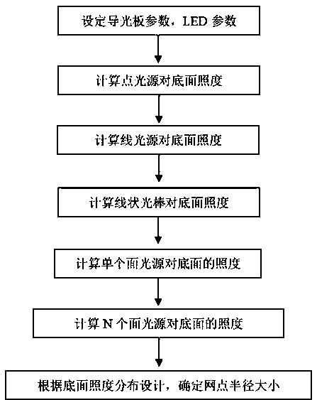
[0063] Please refer to figure 1 , the present invention provides a design method for dot distribution on the bottom surface of a side-entry light guide plate:

[0064] Step 1: Set LED parameters and light guide plate parameters. LED parameters include LED length b, width a initial direct light intensity I 0 and the center distance between two LED lamps l N , the parameters of the light guide plate include the length, width, thickness and material of the light guide plate.

[0065] The second step: Calculating the point light source is to regard the LED light source as a point light source, and its illuminance to a line on the bottom surface. From figure 2 The following known conditions can be obtained:

[0066]

[0067] Among them, h is the height of the point light source, L is the vertical distance between the desired point and the side of the light guide plate, and θ is the angle between the horizontally incident light and the obliquely incident light on the bottom...


PUM


Abstract

The invention relates to a design method for the bottom surface lattice point distribution of an edge-lighting light guide plate. The method includes the following steps that: light guide plate parameters and LED parameters are set; the illuminance of point light sources relative the bottom of the light guide plate is calculated; the illuminance of linear light sources relative the bottom of the light guide plate is calculated by means of integral computation according to the illuminance of the point light sources relative the bottom of the light guide plate, and the illuminance of linear optical stick light sources relative to the bottom of the light guide plate is obtained by means of fitting according to the condition of total reflection; and the illuminance of a single area light source relative to the bottom of the light guide plate is calculated by means of integral computation according to the illuminance of the linear light sources relative the bottom of the light guide plate;and the illuminance of n area light sources relative to the bottom of the light guide plate is calculated, and the radius of a point at any coordinate position is obtained according to the illuminanceof the n area light sources relative to the bottom of the light guide plate on the basis of the law of conservation of energy. With the design method of the invention adopted, the illuminance value of a certain point at the bottom of the light guide plate can be calculated accurately and efficiently according to the given LED parameters and the parameters of the light guide plate, and the point layout of uniform lighting light emission can be calculated.

Description

technical field [0001] The invention relates to the field of light plate scattering dots, in particular to a method for designing the distribution of dots on the bottom surface of a side-entry light guide plate. Background technique [0002] In recent years, liquid crystal display technology has gradually replaced the traditional cathode ray tube display technology due to its light and thin product volume, small footprint, and low radiation, and has occupied the mainstream of flat panel display products. A liquid crystal display (LCD) is not an active light-emitting display device, and needs a backlight module to provide illumination for it to display images. The function of the backlight module is to pass the light emitted by the point light source or the line light source through the light guide plate (LGP) to form the surface light source required by the liquid crystal display, which determines the light efficiency, uniformity and color characteristics of the liquid cryst...

Claims


Application Information

Patent Timeline
Patent Type & Authority Patents(China)
IPC IPC(8): G02B6/00
CPCG02B6/004G02B6/0065
Inventor 陈恩果吕成林黄佳敏江宗钊游耀堂柳钟旭林淑颜林鉴垚
Owner FUZHOU UNIV
Learn More