Fiber stretching device and fiber delayed scanning system

A stretching device and scanning system technology, applied in the field of optical communication, can solve the problems of optical path difference, small scanning range, etc., and achieve the effects of increasing transmission length, increasing optical path scanning range, and increasing stretching length

Inactive Publication Date: 2018-11-16
SHENZHEN CCT THZ TECH CO LTD +1
View PDF9 Cites 2 Cited by
  • Summary
  • Abstract
  • Description
  • Claims
  • Application Information

AI Technical Summary

Problems solved by technology

[0006] The purpose of the present invention is to provide an optical fiber stretching device to solve the technical problem of the small optical path difference scanning range in the prior art

Method used


Image

  • Fiber stretching device and fiber delayed scanning system
  • Fiber stretching device and fiber delayed scanning system
  • Fiber stretching device and fiber delayed scanning system

Examples


Embodiment Construction

[0028] In order to make the technical problems, technical solutions and beneficial effects to be solved by the present invention clearer, the present invention will be further described in detail below in conjunction with the accompanying drawings and embodiments. It should be understood that the specific embodiments described here are only used to explain the present invention, not to limit the present invention.

[0029] It should be noted that when an element is referred to as being “disposed on” another element, it may be directly on the other element or indirectly on the other element. When an element is referred to as being "connected to" another element, it can be directly connected to the other element or indirectly connected to the other element. In addition, the terms "first" and "second" are used for descriptive purposes only, and cannot be interpreted as indicating or implying relative importance or implicitly specifying the quantity of indicated technical features...


PUM


Abstract

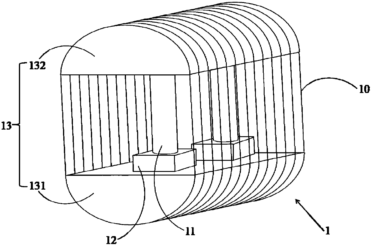
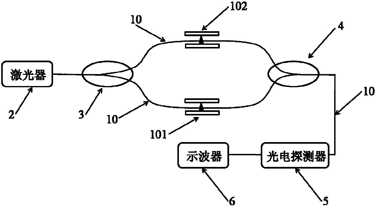
The present invention relates to the technical field of optical communication and provides a fiber stretching device and a fiber delayed scanning system. The fiber stretching device includes a telescopic rod, a motor that can drive the telescopic rod to stretch and retract, and a telescopic portion for winding a fiber. One end of the telescopic rod is connected with the motor, and the other end ofthe telescopic rod is connected with the telescopic portion and can expand or shrink the telescopic portion. The fiber is wound around the outer surface of the telescopic portion. The telescopic rodis driven by the motor to move, and then the telescopic portion is driven to move so as to stretch the fiber. Thus, the stretched length of the fiber can be increased and the transmission length of laser light in the fiber is further increased, thereby expanding an optical path scanning range.

Description

technical field [0001] The invention relates to the technical field of optical communication, and more specifically, relates to an optical fiber stretching device and an optical fiber delay scanning system. Background technique [0002] In the traditional Fourier transform spectrometer, the movement of the mirror is generally used to scan the optical path difference; in the fiber-optic Fourier transform spectrometer, the early research work also used the mirror as the optical path difference scanning component. With the development of technology, it is proposed to replace the mirror with an all-fiber Fourier Transform Spectrometer (FFTS) without moving parts, so as to overcome the shortcomings of the mirror moving and scanning. [0003] In FFTS, the optical fiber is used to replace the traditional optical path, the coupler replaces the beam splitter, and the fiber stretcher replaces the mirror to move, so as to realize the phase modulation. The schemes of phase modulation t...

Claims


Application Information

Patent Timeline
Patent Type & Authority Applications(China)
IPC IPC(8): G02B26/06
CPCG02B26/06
Inventor 祁春超杨正华吴光胜谭信辉
Owner SHENZHEN CCT THZ TECH CO LTD
Why Eureka
Try Eureka