Supercharge Your Innovation With Domain-Expert AI Agents!

Beam forming antenna

A beamforming and antenna technology, applied in the field of beamforming antennas, can solve the problem of slow roll-off speed of antenna lobe width and lobe width

Inactive Publication Date: 2018-11-16
HUAWEI TECH CO LTD
View PDF9 Cites 2 Cited by
  • Summary
  • Abstract
  • Description
  • Claims
  • Application Information

AI Technical Summary

Problems solved by technology

To solve the problems of wide lobe width and slow lobe width roll-off speed of existing antennas

Method used


Image

  • Beam forming antenna
  • Beam forming antenna
  • Beam forming antenna

Examples


Embodiment Construction

[0033] The following will clearly and completely describe the technical solutions in the embodiments of the application with reference to the drawings in the embodiments of the application. Apparently, the described embodiments are only some of the embodiments of the application, not all of them. Based on the embodiments in this application, all other embodiments obtained by persons of ordinary skill in the art without creative efforts fall within the protection scope of this application.

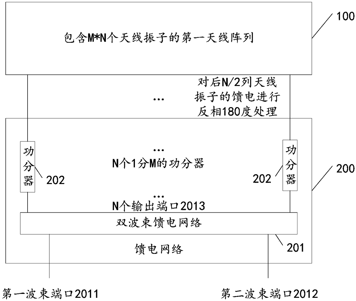
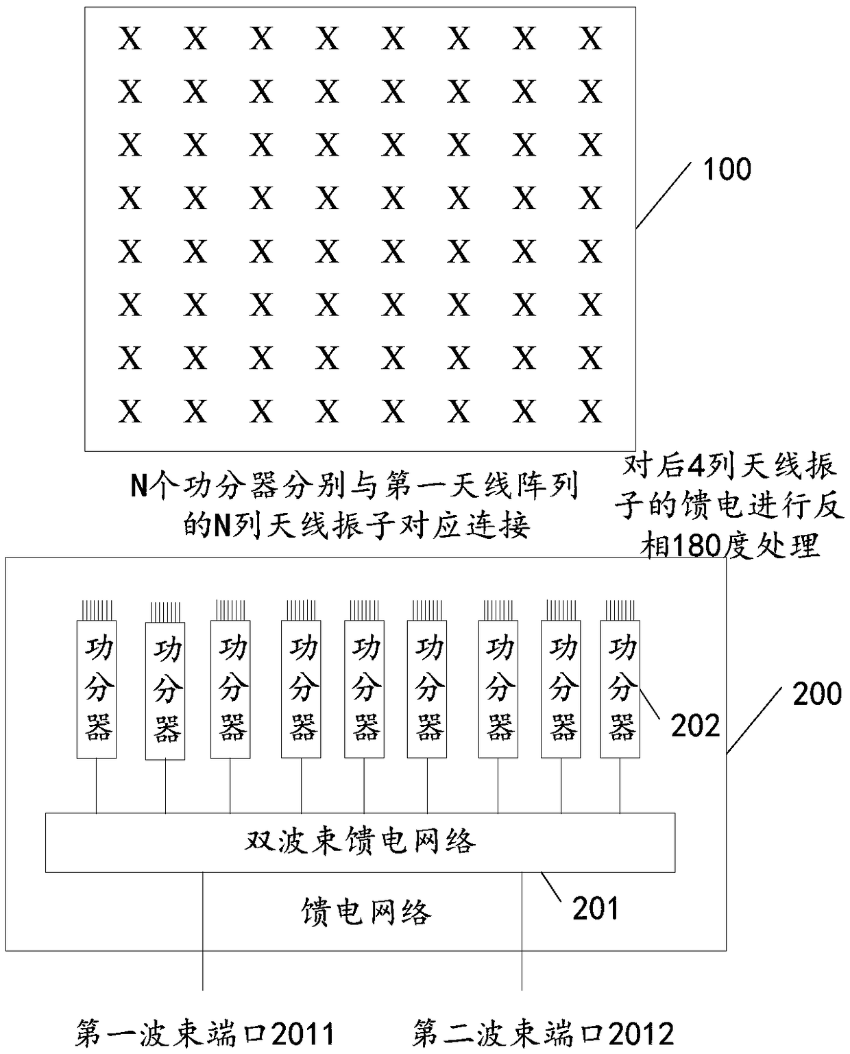
[0034] Please refer to figure 1 , which is a schematic diagram of the composition of a beamforming antenna provided in the embodiment of the present application; it may include:

[0035] The first antenna array 100 and the first feed network 200;

[0036] The first antenna array 100 includes M*N antenna elements, and both M and N are integers greater than or equal to 6;

[0037] The first feed network 200 includes a dual-beam feed network 201 and N power dividers 202 of 1 and M, and the d...


PUM


Abstract

The embodiment of the invention discloses a beam forming antenna. The beam forming antenna comprises an antenna array and a feed network, wherein the antenna array comprises M*N antenna oscillators, wherein M and N are greater than or equal to 6 respectively; the feed network comprises a dual-beam feed network and N power dividers capable of dividing one into M, the dual-beam feed network comprises a first beam port, a second beam port and N output ports, the N output ports are connected with the input ports of the N power dividers respectively, and the output ports of the N power dividers arecorrespondingly connected with the N lines of antenna oscillators respectively; when a feed signal input at the first beam port or the second beam port is used for feeding the N lines of antenna oscillators, an arithmetic progression is formed by the phase distribution of the N lines of antenna oscillators by carrying out reversal 180-degree treatment on the feeding of later N / 2 lines of antennaoscillators. By adopting the beam forming antenna, dual narrow beams and the forming antenna with rapid roll-off characteristic can be realized.

Description

technical field [0001] The invention relates to the technical field of communication, in particular to a beam-forming antenna. Background technique [0002] Beamforming can generate directional beams by adjusting the weighting coefficients of each element in the antenna array, so that specific pattern characteristics can be obtained. Therefore, beamforming technology has great advantages in expanding coverage, improving edge throughput, and interference suppression. When the beamforming antenna is used in crowded scenes such as high-density venues, the beamforming antenna is usually required to have the characteristics of fast beam roll-off and low side lobes, so as to reduce the interference between different sectors. [0003] Existing beamforming antennas usually have a wider lobe width, and the roll-off speed of the lobe width is slower, resulting in greater interference. With the improvement of capacity requirements, it has gradually been unable to meet customer needs,...

Claims


Application Information

Patent Timeline
Patent Type & Authority Applications(China)
IPC IPC(8): H01Q15/24H01Q21/00H01Q21/06
CPCH01Q15/24H01Q21/0006H01Q21/061
Inventor 许海堤罗勇王萍高文军马炳刘志佳
Owner HUAWEI TECH CO LTD
Features
  • R&D
  • Intellectual Property
  • Life Sciences
  • Materials
  • Tech Scout
  • Unparalleled Data Quality
  • Higher Quality Content
  • 60% Fewer Hallucinations
Learn More