Micro-energy grid multi-objective planning method based on power-to-gas technology and renewable energy utilization

A technology of renewable energy and multi-objective planning, which is applied in the field of multi-objective planning of micro-energy networks considering power-to-gas technology and renewable energy utilization, and can solve problems that have not been fully studied

Active Publication Date: 2018-11-16
TIANJIN UNIV
View PDF3 Cites 23 Cited by
  • Summary
  • Abstract
  • Description
  • Claims
  • Application Information

AI Technical Summary

Problems solved by technology

At present, the application of P2GSS in microgrid has been studied in depth, but the application of P2GSS in microenergy grid considering multiple energy coupling has not been fully studied.

Method used


Image

  • Micro-energy grid multi-objective planning method based on power-to-gas technology and renewable energy utilization
  • Micro-energy grid multi-objective planning method based on power-to-gas technology and renewable energy utilization
  • Micro-energy grid multi-objective planning method based on power-to-gas technology and renewable energy utilization

Examples


Embodiment 1

[0095] In order to effectively realize the multi-objective planning of the micro-energy network including P2GSS and renewable energy, the present invention provides a multi-objective planning method for the micro-energy network considering the power-to-gas technology and the utilization of renewable energy, as described below for details:

[0096] 101: Modeling of Key Devices in Micro Energy Grids

[0097] (1) Electrolytic hydrogen model

[0098] In the process of hydrogen production from alkaline water electrolysis, the relationship between the output of hydrogen and oxygen and the input of electric energy is:

[0099]

[0100]

[0101] In the formula: V H2 , V O2 are the production rates of hydrogen and oxygen, respectively, Nm 3 ·h -1 ;P Ele is the electric power of the input electrolytic hydrogen; η Ele is the hydrogen conversion factor of the electrolytic hydrogen unit.

[0102] (2) Fuel cell model

[0103] The relationship between the power output of the fu...

Embodiment 2

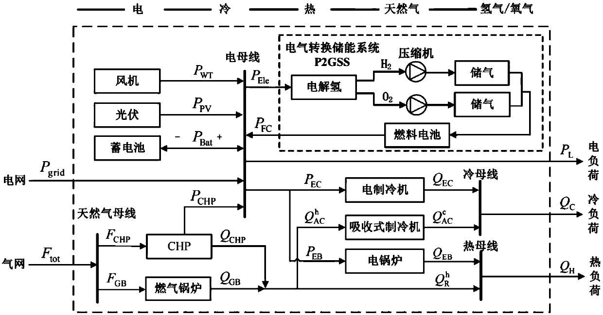
[0166] First set the scene, scene 1 does not consider energy storage, including figure 1 All equipment except P2GSS and storage battery; Scenario 2, adding storage battery on the basis of Scenario 1; Scenario 3, adding P2GSS on the basis of Scenario 1; Scenario 4, the micro-energy network structure is as follows figure 1 As shown, consider battery and P2GSS for energy storage;

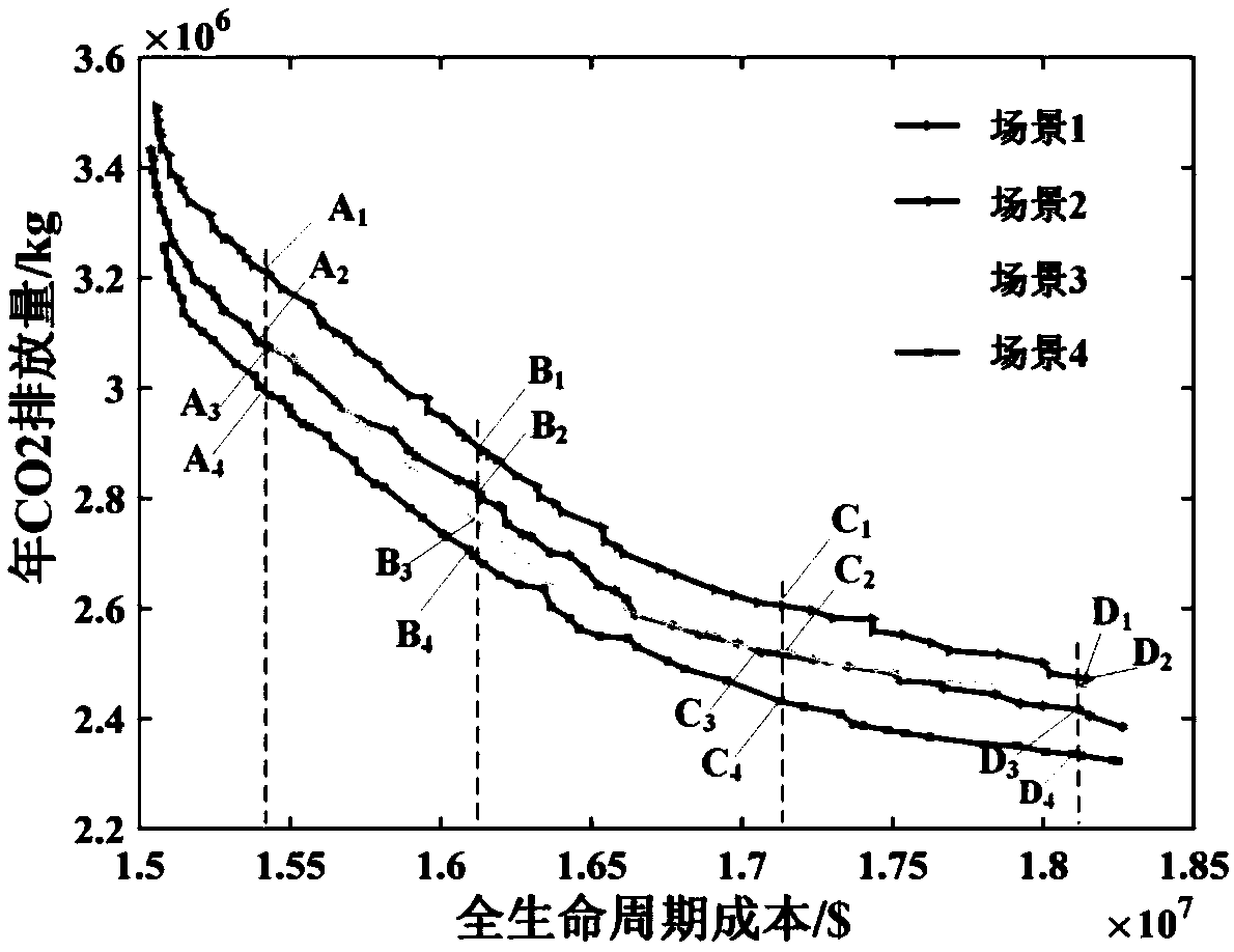
[0167] The Pareto optimal planning scheme set of the micro-energy grid in different scenarios is obtained through optimization. First, the scenarios 1 to 4 are analyzed to compare the performance of the micro-energy grid planning schemes under different energy storage methods, and then the scenarios 4 and 5 are compared. To analyze the relationship between the renewable energy integration of the micro-energy grid and the performance such as economic cost.

[0168] The Pareto front of Scenario 1-Scenario 4 is as image 3 shown. In the same scenario, the solutions in the Pareto optimal solution set ar...


PUM


Abstract

The invention relates to the fields of micro-energy grid and distributed energy planning, provides a micro-energy grid multi-objective planning method considering a power-to-gas technology and renewable energy utilization, and has the guiding significance for micro-energy grid planning comprising a wind generator, photovoltaic, cooling, heating and power combined system, a P2GSS, a storage batteryand the like. The invention discloses the micro-energy grid multi-objective planning method based on the power-to-gas technology and renewable energy utilization; the method comprises the steps that(1) modeling of a micro-energy grid is carried out; (2) the whole life cycle cost of the micro-energy grid is calculated on the basis of a full life cycle method, wherein the minimum total life cyclecost, and the lowest annual carbon dioxide emission amount are taken as an optimization objective, and the influence of the electric refrigeration proportion and the electric heating proportion and other operation modes is considered, and a multi-objective optimization configuration method aiming at the capacity of the key equipment of the micro-energy grid is established; and (3) the multi-objective planning method for the micro-energy grid is provided through comparison of different scenes. The method is mainly applied to the micro-energy grid and distributed energy planning occasions.

Description

technical field [0001] The invention relates to the fields of micro-energy network and distributed energy planning, in particular to a multi-objective planning method for a micro-energy network considering power-to-gas technology and renewable energy utilization. Background technique [0002] In recent years, the fossil energy crisis and environmental pollution problems have become increasingly prominent. The proposal of the concept of energy Internet provides a new idea for solving energy and environmental problems, which has aroused extensive attention at home and abroad. Micro-energy network is an important form of energy Internet, and it is the end network of energy utilization. It is characterized by distributed energy development and on-site consumption, and is widely used in industrial parks, large buildings, urban and rural concentrated residential areas and many other scenarios. [0003] There are many devices in the micro-energy grid, and different forms of energy...

Claims


Application Information

Patent Timeline
Patent Type & Authority Applications(China)
IPC IPC(8): H02J3/38H02J3/28H02J3/32
CPCH02J3/382H02J3/383H02J3/386H02J3/387H02J3/28H02J3/32H02J2203/20H02J3/388Y02E70/30Y02E10/56Y02E10/76
Inventor 王丹刘维康余晓丹王伟亮薛松
Owner TIANJIN UNIV
Why Eureka
Try Eureka