Slot bottom via hole solder resist plugging-based manufacturing method and PCB

A production method and solder mask technology, which are applied in the manufacture of printed circuits, electrical connection of printed components, electrical components, etc., can solve the problems of uneven oil leakage and uneven force in plug holes, and avoid long production process and oil leakage. Uniform and simple production process

Active Publication Date: 2018-11-16
DONGGUAN SHENGYI ELECTRONICS
View PDF2 Cites 2 Cited by
  • Summary
  • Abstract
  • Description
  • Claims
  • Application Information

AI Technical Summary

Problems solved by technology

[0003] The invention provides a method for making a slot bottom via hole solder resist plug hole and a PCB, so as to solve the problem of uneven oil emission from the plug hole in the prior art due to the uneven stress on the bottom of the slot and the outside of the slot.

Method used


Image

  • Slot bottom via hole solder resist plugging-based manufacturing method and PCB
  • Slot bottom via hole solder resist plugging-based manufacturing method and PCB
  • Slot bottom via hole solder resist plugging-based manufacturing method and PCB

Examples


Embodiment 1

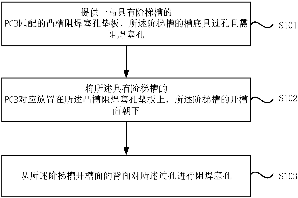
[0035] see figure 1 , the present embodiment 1 provides a method for making a solder resist plug hole in a groove bottom via, which specifically includes the following steps:

[0036] S101. Provide a protruding groove solder resist plug hole backing plate matching the PCB with stepped grooves, the bottom of the stepped groove has via holes and solder resist plug holes are required.

[0037] In one embodiment, preferably, S101 further includes:

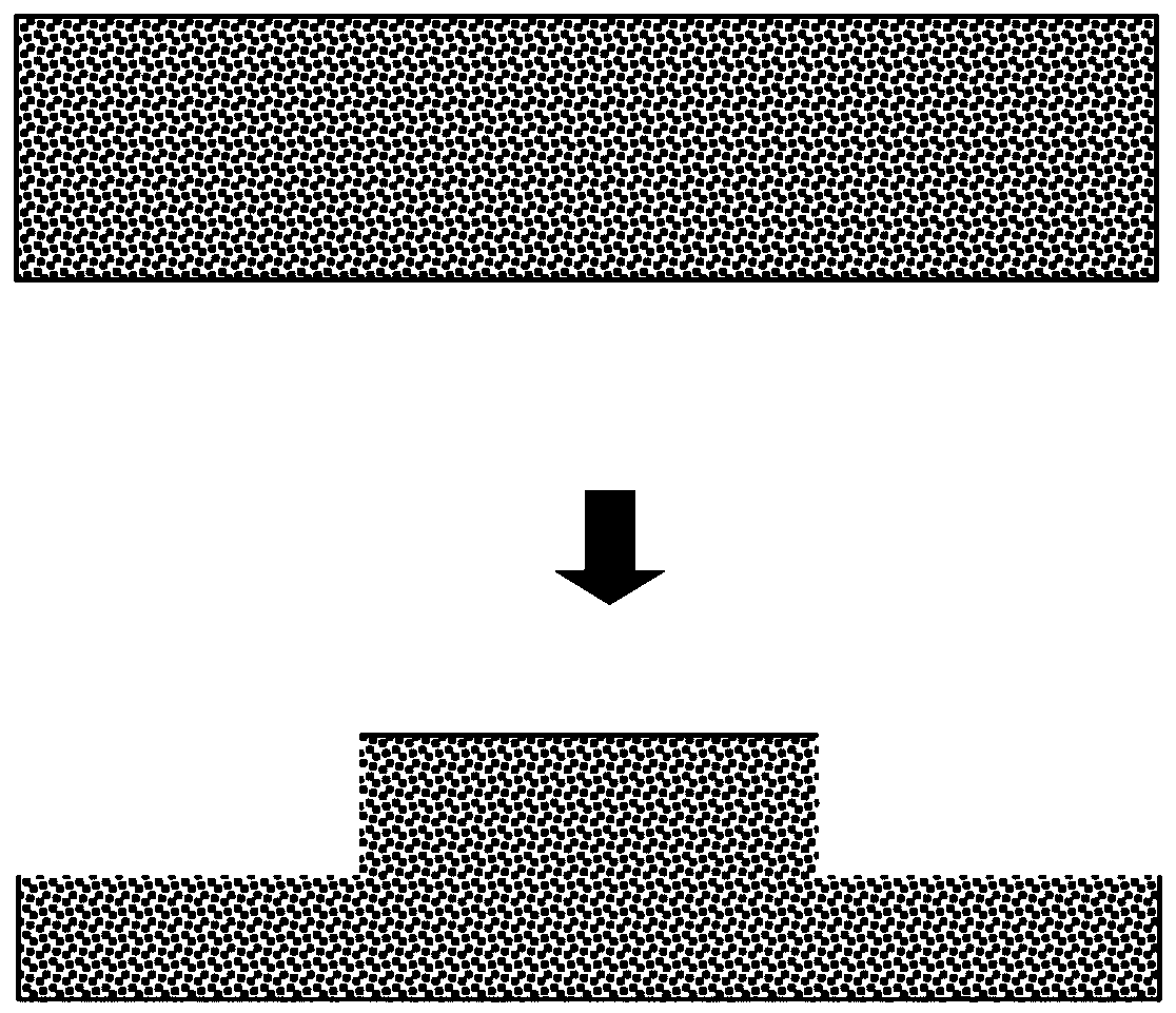
[0038] (1) Carry out the controlled depth milling of the first backing plate, the depth is the depth of the stepped groove to form a convex groove backing plate, and the position of the convex groove corresponds to the position of the stepped groove, such as figure 2 shown.

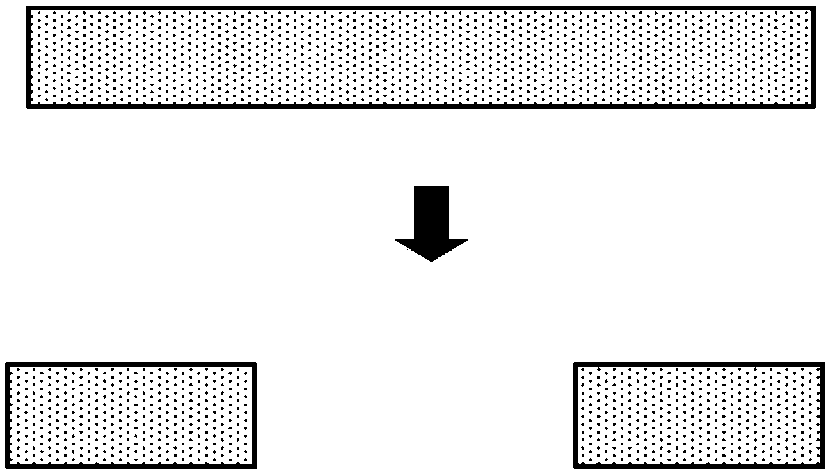
[0039] (2) opening the part of the second backing plate corresponding to the position of the step groove to form a covering backing plate, the thickness of the covering backing plate is the same as the depth of the step groove, as Figure 3-4 shown.

[0040] ...

Embodiment 2

[0050] The second embodiment provides a PCB, which includes a slot bottom via hole of a solder resist plug hole, and the slot bottom via hole of the solder resist plug hole is manufactured according to the manufacturing method provided in the first embodiment.

[0051] Compared with the prior art, the PCB provided by the embodiment of the present invention not only solves the problem of uneven stress on the bottom of the groove and outside the groove when the hole is plugged, but also ensures that the plug hole emits oil evenly, and at the same time avoids the use of resin plug holes. The production process is long, the production efficiency is low, and the production cost is high. The production process is simpler and suitable for mass production.


PUM


Abstract

The embodiments of the present invention disclose a slot bottom via hole solder resist plugging-based manufacturing method and a PCB. The method includes the following steps that: a protruding slot solder resist plug base plate matched with a PCB having a stepped trench is provided, a via hole is formed in the slot bottom of the stepped slot, wherein the via hole requires to be plugged with solderresist; the PCB having the stepped slot is correspondingly arranged on the protruding slot solder resist plug base plate with the slotted surface of the stepped slot facing downwards; and the via hole is plugged with the solder resist from the back surface of the slotted surface of the stepped slot. With the manufacturing method provided by the technical schemes provided by the embodiments of theinvention adopted, a problem that the bottom of the slot and the exterior of the slot are unevenly stressed during hole plugging can be solved; uniform oil bleeding in hole plugging can be ensured; and the problems of long production process, low production efficiency and high production cost of a resin hole plugging technique can be solved. The method of the invention has the advantages of simple production technique and suitability for batch production.

Description

technical field [0001] Embodiments of the present invention relate to the technical field of printed circuit boards, and in particular to a method for manufacturing slot-bottom via-hole solder-resisting plug holes and a PCB. Background technique [0002] Due to the limitation of the height difference of the stepped grooves, the vias at the bottom of the stepped grooves cannot be plugged from the grooved surface, so the holes must be plugged from the back of the grooved. Plugging the hole from the back of the slot has uneven force inside and outside the slot, which will lead to uneven oil leakage, especially at the bottom of the slot, which is prone to serious oil leakage and pollutes the bottom of the groove; or less oil from the bottom of the groove, resulting in leakage blocked situation. Therefore, it is generally not to make solder resist plug holes at the bottom of the groove, but to replace them with resin plug holes. For stepped grooves, resin plug holes must be made...

Claims


Application Information

Patent Timeline
Patent Type & Authority Applications(China)
IPC IPC(8): H05K3/00H05K1/11
CPCH05K1/115H05K3/0094H05K2201/0959
Inventor 焦其正纪成光王洪府王小平刘传金胡源
Owner DONGGUAN SHENGYI ELECTRONICS
Why Eureka
Try Eureka