Cooling base for communication device
A technology for equipment and communication, applied in the field of communication equipment, can solve the problems of reducing the service life of communication equipment, high heat of communication equipment, damage to communication equipment, etc., and achieve the effect of prolonging service life, convenient use and convenient use
- Summary
- Abstract
- Description
- Claims
- Application Information
AI Technical Summary
Problems solved by technology
Method used
Image
Examples
Embodiment 1
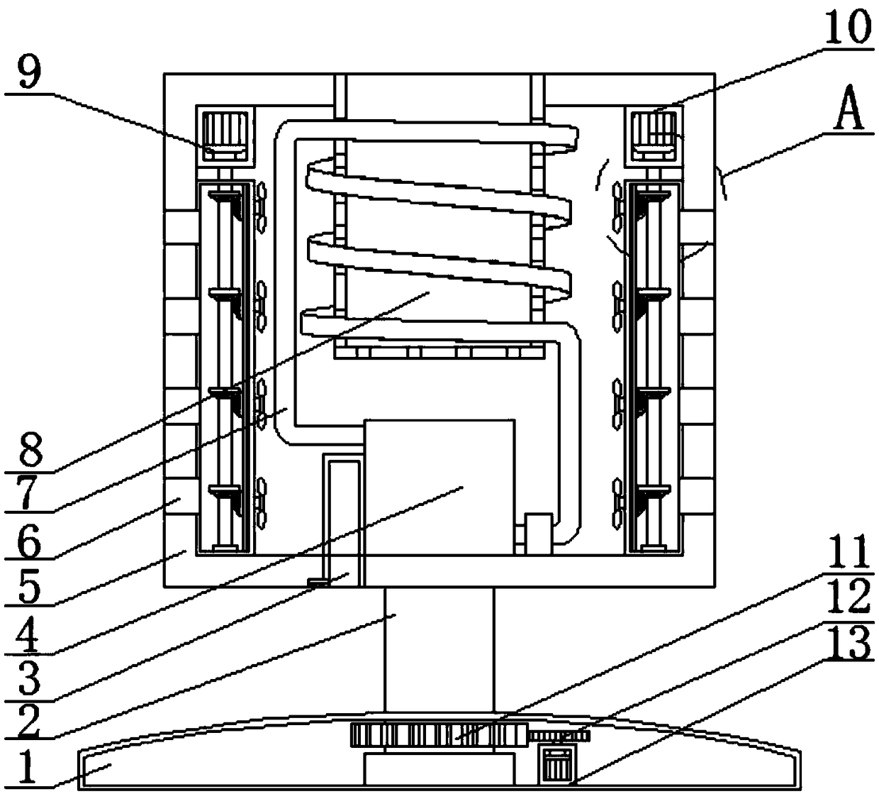
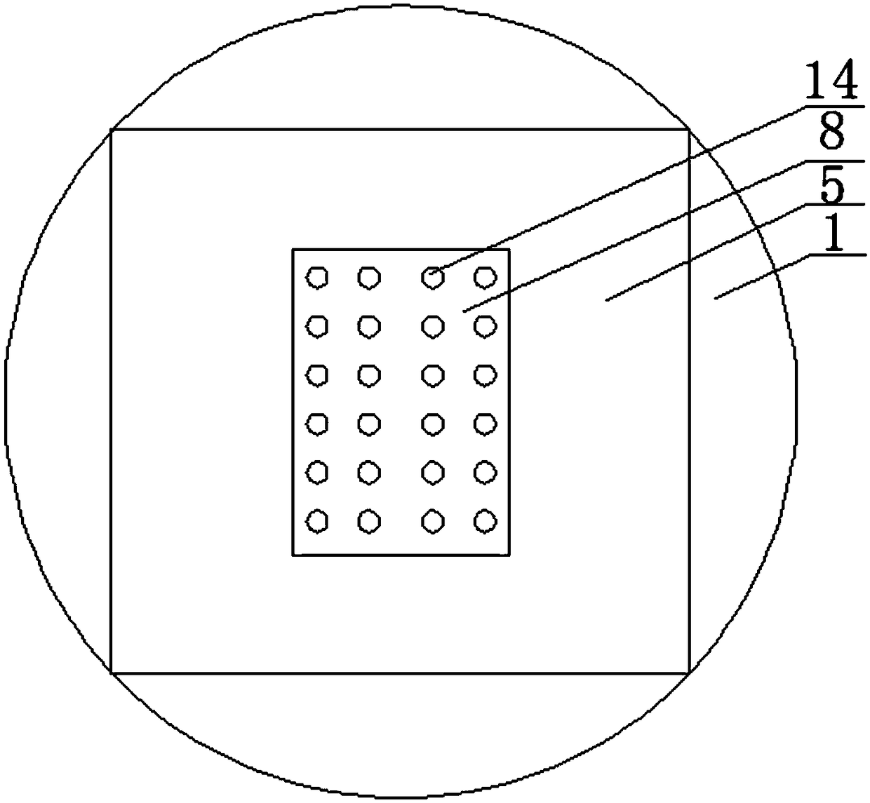
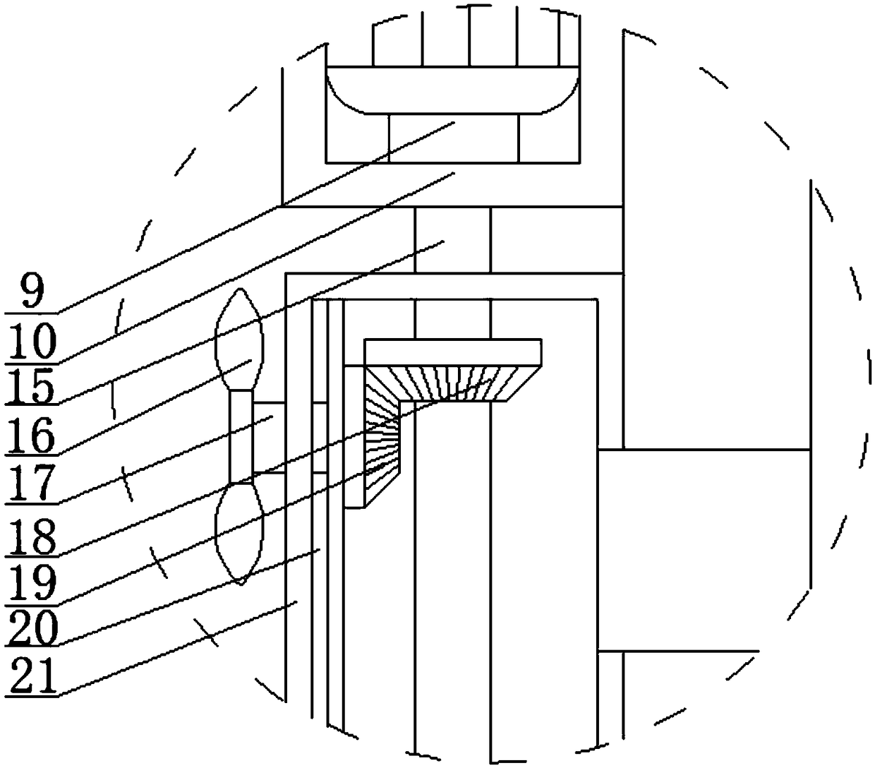
[0023] refer to figure 1 , 2 , 3, a cooling base for communication equipment, including a base plate 1 and a mounting block 5, the side walls at both ends of the mounting block 5 and the side walls at both ends of the two placement boxes 21 are provided with air inlet holes, and the mounting block 5 There is a cavity inside, the bottom in the cavity is fixed with a water tank 4, the upper end of the mounting block 5 is provided with a groove 8, and a plurality of air outlet holes 14 are arranged at equal intervals on the bottom of the groove 8 and on the side wall of the week. The number of air holes 14 is 36-56, one end of the water tank 4 is installed with a circulating water pipe 7, a water pump is installed on the circulating water pipe 7, and the circulating water pipe 7 is set on the groove 8, and one end of the circulating water pipe 7 is installed on the water tank 4 On the other end, the water cooling belt is used to reduce the temperature in the base to achieve the ...
Embodiment 2
[0026] refer to figure 1 , 2 , 3, a cooling base for communication equipment, including a base plate 1 and a mounting block 5, the side walls at both ends of the mounting block 5 and the side walls at both ends of the two placement boxes 21 are provided with air inlet holes, and the mounting block 5 There is a cavity inside, the bottom in the cavity is fixed with a water tank 4, the upper end of the mounting block 5 is provided with a groove 8, and a plurality of air outlet holes 14 are arranged at equal intervals on the bottom of the groove 8 and on the side wall of the week. The number of air holes 14 is 36-56, one end of the water tank 4 is installed with a circulating water pipe 7, a water pump is installed on the circulating water pipe 7, and the circulating water pipe 7 is set on the groove 8, and one end of the circulating water pipe 7 is installed on the water tank 4 On the other end, the water cooling belt is used to reduce the temperature in the base to achieve the ...
Embodiment 3
[0030] refer to figure 1 , 2, 3, a cooling base for communication equipment, including a base plate 1 and a mounting block 5, the side walls at both ends of the mounting block 5 and the side walls at both ends of the two placement boxes 21 are provided with air inlet holes, and the mounting block 5 There is a cavity inside, the bottom in the cavity is fixed with a water tank 4, the upper end of the mounting block 5 is provided with a groove 8, and a plurality of air outlet holes 14 are arranged at equal intervals on the bottom of the groove 8 and on the side wall of the week. The number of air holes 14 is 36-56, one end of the water tank 4 is installed with a circulating water pipe 7, a water pump is installed on the circulating water pipe 7, and the circulating water pipe 7 is set on the groove 8, and one end of the circulating water pipe 7 is installed on the water tank 4 On the other end, the water cooling belt is used to reduce the temperature in the base to achieve the e...
PUM
 Abstract
Description
Claims
Application Information
 - R&D
- Intellectual Property
- Life Sciences
- Materials
- Tech Scout
- Unparalleled Data Quality
- Higher Quality Content
- 60% Fewer Hallucinations
Browse by: Latest US Patents, China's latest patents, Technical Efficacy Thesaurus, Application Domain, Technology Topic, Popular Technical Reports.
© 2025 PatSnap. All rights reserved.Legal|Privacy policy|Modern Slavery Act Transparency Statement|Sitemap|About US| Contact US: help@patsnap.com


