

Smart electric toothbrush
An intelligent electric toothbrush and electric toothbrush technology are applied in dentistry, tooth cleaning, medical science, etc., which can solve the problems of low cleaning efficiency and time-consuming, and achieve the effect of improving cleaning efficiency, improving cleaning efficiency and cleaning effect
- Summary
- Abstract
- Description
- Claims
- Application Information
AI Technical Summary
Problems solved by technology
Method used
Image

Examples
Embodiment 1
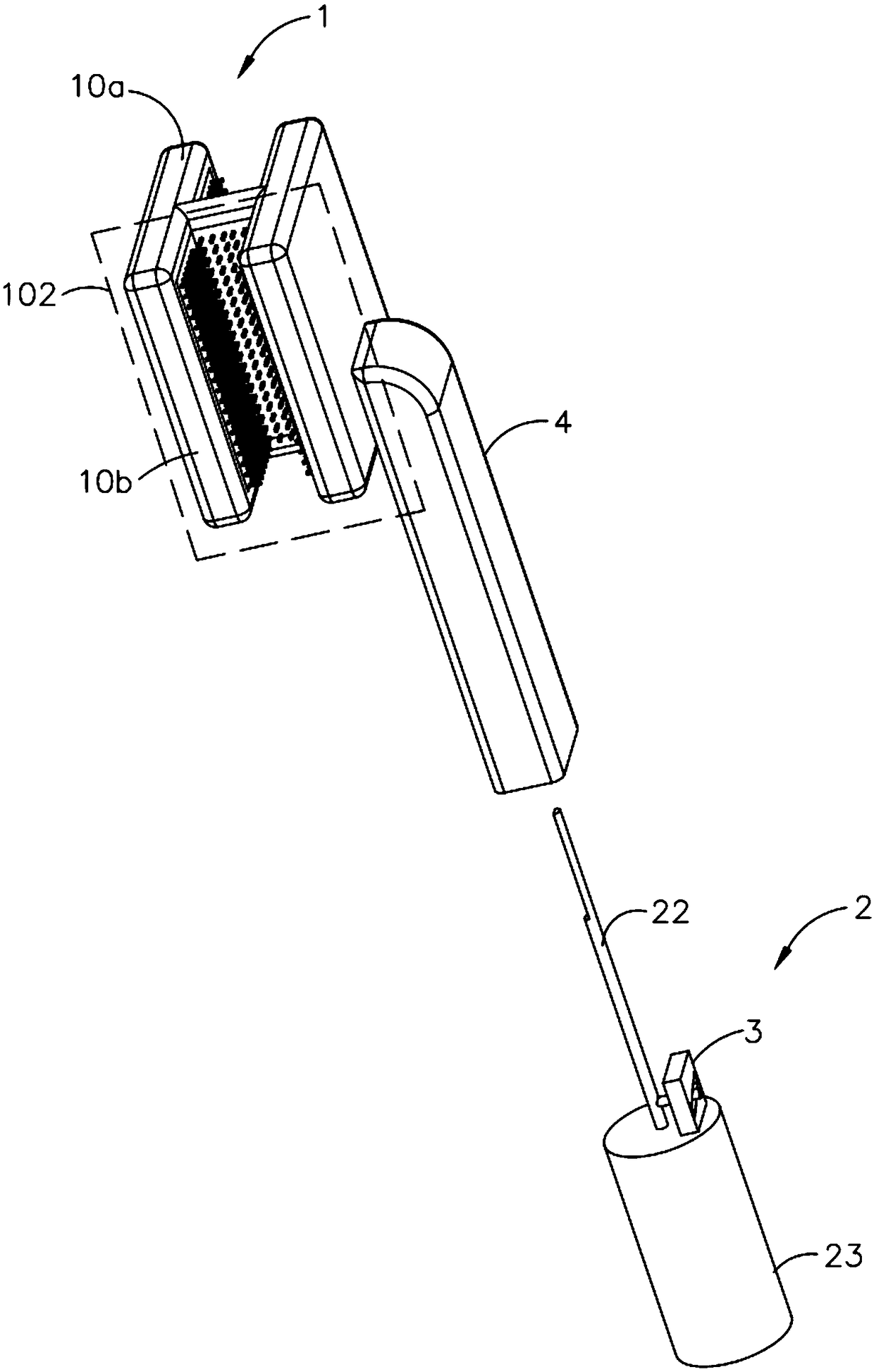
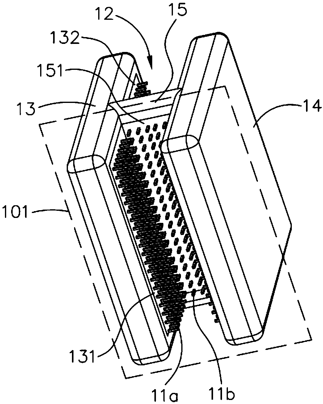
[0054] Please also refer to figure 1 as well as figure 2 , is a structural schematic diagram of an intelligent electric toothbrush provided by the present invention. The smart electric toothbrush includes a brush head part 1 and a drive part 2. The brush head part 1 includes a brush head frame and bristles. The brush head frame is provided with an engaging groove 12 for teeth to occlude. The two sides of setting, bristle comprises first bristle 11a and second bristle 11b, and first bristle 11a is arranged on two sides, and second bristle 11b is arranged on bottom surface, and first bristle 11a, second bristle 11b are respectively used for cleaning different teeth. surface. The driving part 2 includes a driving mechanism and a driving shaft 22. One end of the driving shaft 22 is connected to the driving mechanism, and the other end of the driving shaft 22 is connected to the brush frame. The driving mechanism is used to drive the driving shaft 22 to drive the brush frame to ...
Embodiment 2
[0080] see Figure 9 , is a structural schematic diagram of an intelligent electric toothbrush provided by the present invention. The smart electric toothbrush includes a brush head part 1 and a drive part 2 . The brush head part 1 includes a brush head skeleton and bristles, and the brush head skeleton is provided with an engaging groove 12 for engaging the teeth. The bristles 11b, the first bristles 11a are arranged on both sides, the second bristles 11b are arranged on the bottom surface, the first bristles 11a and the second bristles 11b are respectively used for cleaning different surfaces of the teeth. The drive part 2 includes a first drive mechanism 21a and a drive shaft 22, one end of the drive shaft 22 is connected to the first drive mechanism 21a, and the other end of the drive shaft 22 is connected to the brush frame, and the first drive mechanism 21a is used to drive the drive shaft 22 along the The axis of the drive shaft 22 rotates.
[0081] Wherein, for the ...
PUM
 Abstract
Description
Claims
Application Information