

Secondary structure pipeline burying building block drilling device
A secondary structure and drilling device technology, applied in the direction of stone processing tools, work accessories, manufacturing tools, etc., can solve the problems of poor control of verticality, difficult combination, and non-compactness, so as to ensure the quality of verticality and reduce labor Strength and the effect of improving construction quality
- Summary
- Abstract
- Description
- Claims
- Application Information
AI Technical Summary
Problems solved by technology
Method used
Image

Examples
Embodiment 1
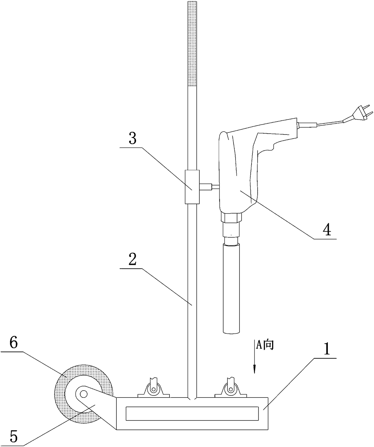
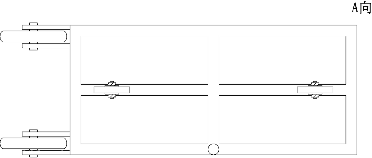
[0019] Embodiment 1: as figure 1 and figure 2 The shown secondary structure pipeline buried block drilling device mainly includes shaped base 1, column 2 and water drill 4 and other components. Each side of the rectangular shaped base 1 is easy to judge that it is parallel to the wall of the room, and it is easy to cooperate with the drilling marking line on the ground, so as to quickly and accurately determine the drilling position, which is conducive to providing stable constraints and positioning for the rhinestone 4 . Among them, the column (1600mm high, 25mm diameter stainless steel pipe) is composed of a shaped base 1. The shaped base 1 is composed of two 500mm long and 25mm diameter stainless steel steel pipes and three 300mm long and 25mm diameter stainless steel steel pipes. The upright column 2 is welded on the shaped base 1. edge centered.
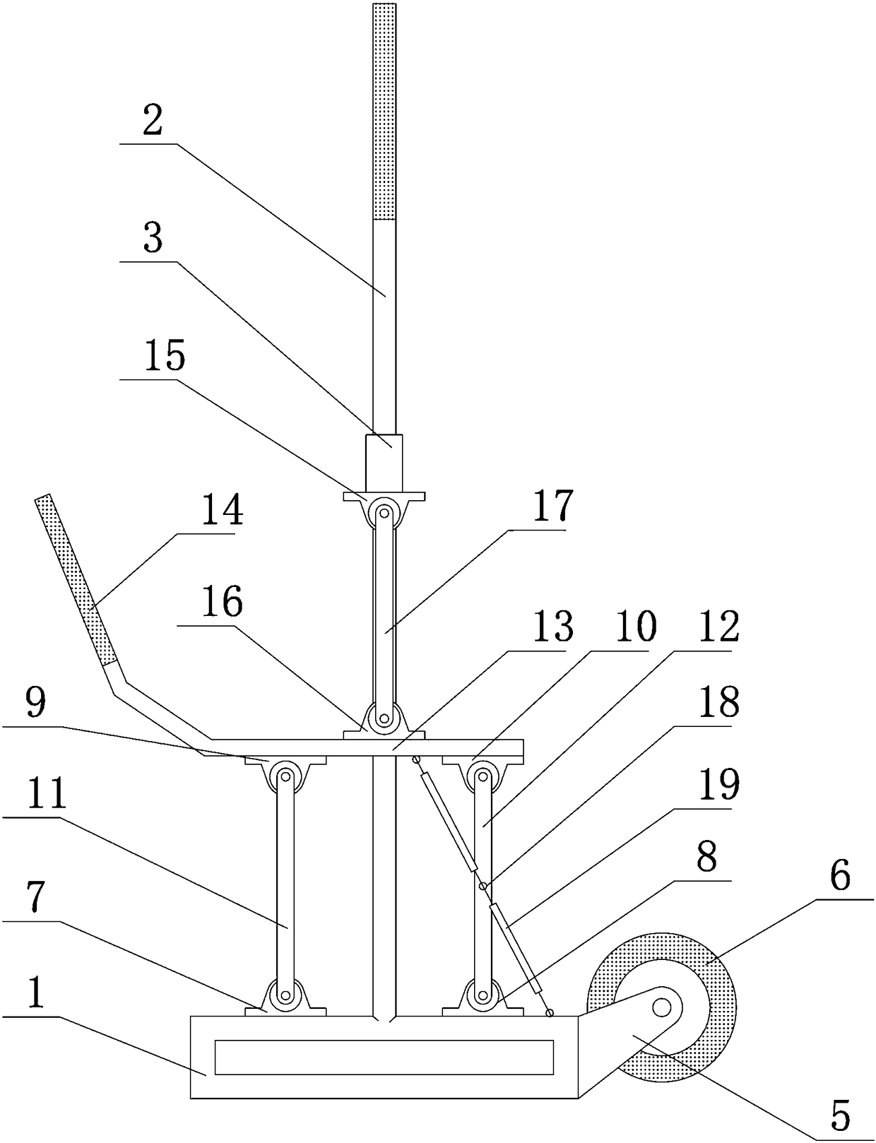
[0020] Such as image 3 Shown: The connecting piece between the rhinestone 4 and the sliding sleeve 3 is welded together b...
Embodiment 2
[0027] Embodiment 2: On the basis of Embodiment 1, a convex-concave guide track is provided between the column 2 and the sliding sleeve 3 . Both the column and the base are composed of stainless steel pipes with a diameter of 25mm. The base is 500mm long and 300mm wide; the casing is a stainless steel pipe with a diameter of 32mm, and the rhinestone is connected to the casing through a screw rod.
[0028] At the same time, a rotating seat is provided at the bottom of the column 2, and the upper section of the column 2 is sleeved in the rotating seat at the bottom thereof, and a locking mechanism is provided on the side of the rotating seat simultaneously. The rotation of the column 2 is constrained by the rotating seat, and the positioning function of the convex-concave guide track can prevent the rhinestone 4 from swinging during the falling process. And when necessary, the working direction of the rhinestone 4 is controlled by adjusting the angle of the swivel seat.
Embodiment 3
[0029] Embodiment 3: On the basis of Embodiment 1 or 2, between the shaping base 1 and the front swing link 11 or the rear swing link 12, or between the movable link 13 and the front swing link 11 or the rear swing link 12 There are extension springs 19 connected between them. Through the action of the extension spring 19, the automatic reduction of the rhinestone 4 and the swing frame can be maintained, further improving the convenience of construction.
PUM
 Abstract
Description
Claims
Application Information