
Wallboard cutting device

A cutting device and wall panel technology, applied in stone processing tools, work accessories, manufacturing tools, etc., can solve problems such as unfavorable production, low efficiency, and environmental pollution, and achieve the effect of reducing labor intensity and improving production efficiency

Pending Publication Date: 2018-11-20
浙江欧舍家居新材股份有限公司
View PDF0 Cites 12 Cited by
  • Summary
  • Abstract
  • Description
  • Claims
  • Application Information

AI Technical Summary

Problems solved by technology

[0002] SPC wallboard is divided into substrate layer, printing layer, wear-resistant layer and UV layer. The connection of each layer is formed by hot compressing and rolling, which completely subverts the glue bonding; the materials used for SPC wallboard are resin powder and calcium powder. Mainly, it is processed through a series of processes such as mixing, high temperature, extrusion, and shaping. The density is between 1.8-2.2, the shrinkage ratio is 1 / 1000, the adhesion force is more than 50 N, and the wear resistance is 12000-15000 rpm. During the heating period, the surface is smoked and scalded between 500 degrees Celsius and 800 degrees Celsius. It is not only practical but also environmentally friendly, and does not contain any volatiles, carcinogens, heavy metals and formaldehyde; the two sides of the wallboard need to be cut off according to actual needs during the production process Edge trimming often uses manual blanking, which is inefficient and not conducive to production, and a large amount of dust will be generated during the trimming process to pollute the environment. A wallboard cutting device is now proposed

Method used


Image

  • Wallboard cutting device
  • Wallboard cutting device
  • Wallboard cutting device

Examples


Embodiment Construction

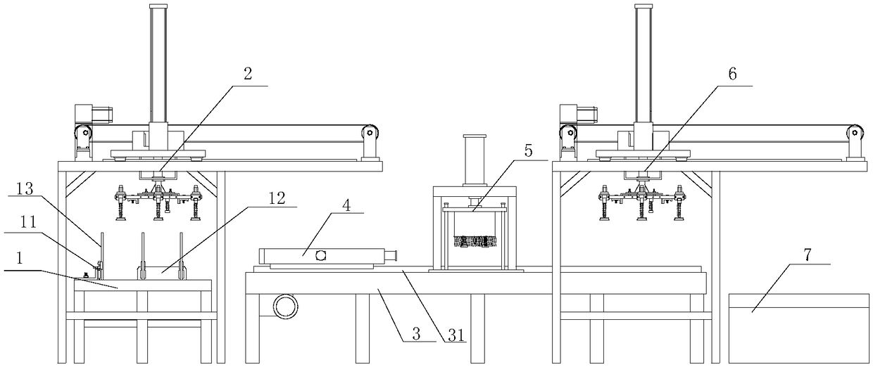
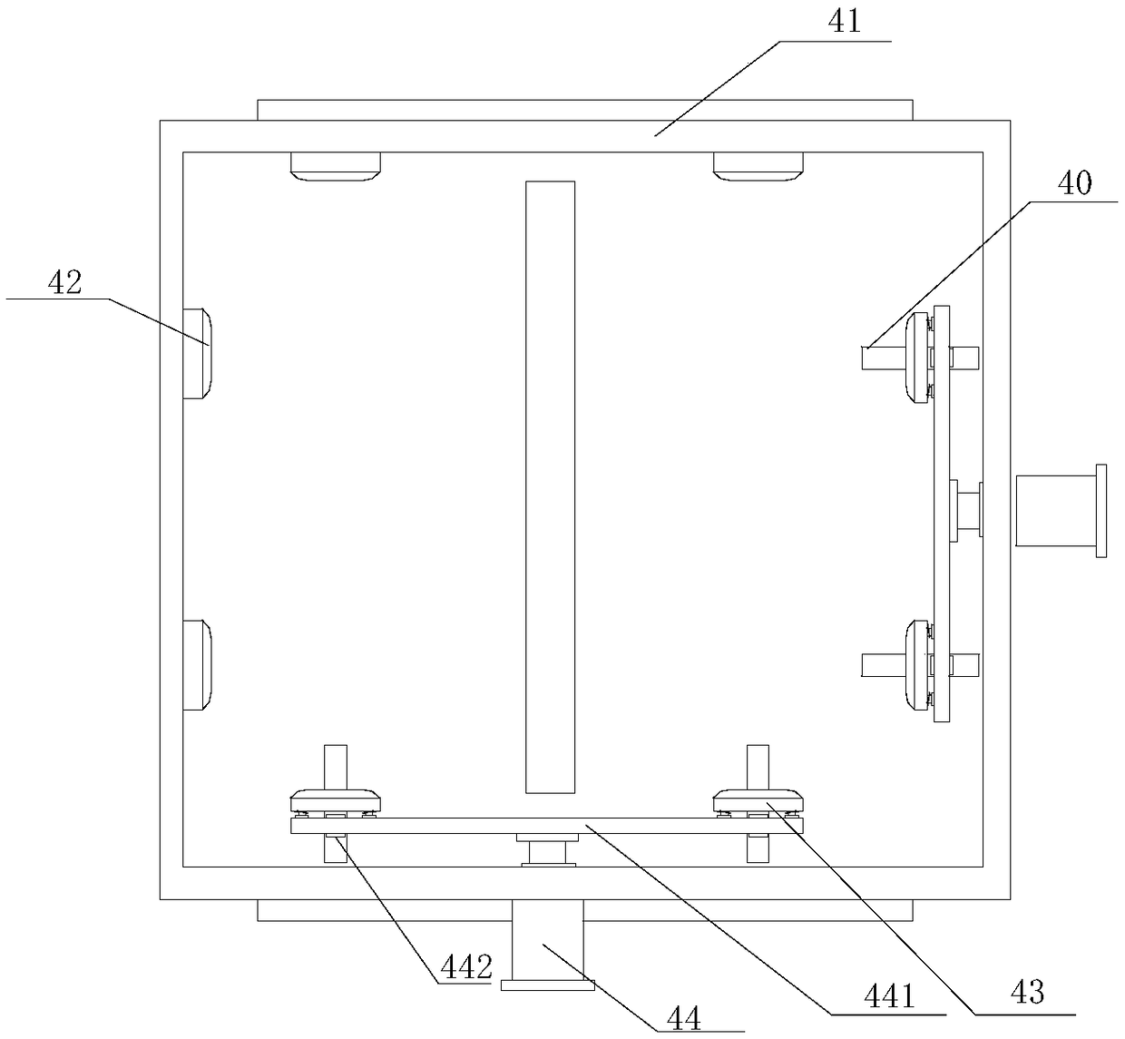
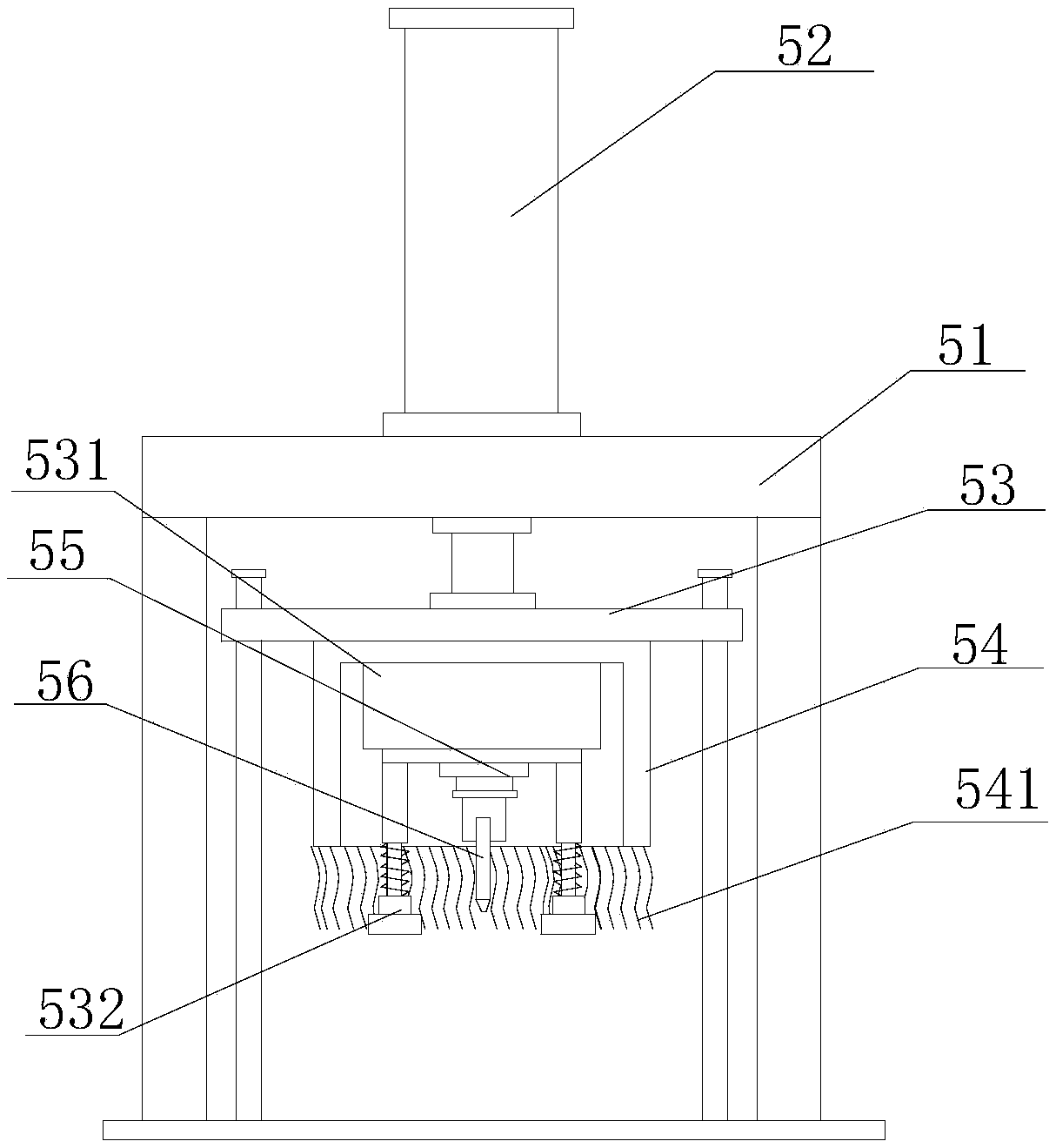
[0020] refer to Figure 1 to Figure 7 , a wallboard cutting device of the present invention, comprising a loading table 1, a vacuum suction cup feeding device 2, a frame 3, a feeding slide 4, a cutting device 5, a vacuum suction cup blanking device 6 and a blanking table 7, the Frame 3 is provided with feeding guide rail 31, and described feeding slide seat 4 is movably installed on feeding guide rail 31, and described feeding slide seat 4 is provided with fixed stopper 42 and movable stopper 43, and described movable stopper The block 43 is installed on the drive plate 441 through the first elastic support, the drive plate 441 is connected with the telescopic rod of the limit cylinder 44, the cutting device 5 is installed on the frame 3, and the cutting device 5 is provided with a A protective cover 54, a cutting knife assembly 56 is installed in the protective cover 54, and the two ends of the frame 3 are respectively provided with a loading platform 1 and a blanking platfor...


PUM


Abstract

The invention provides a wallboard cutting device, comprising a feeding platform, a vacuum cup feeding device, a frame, a feeding sliding seat, a cutting device, a vacuum cup blanking device and a blanking platform; the frame is provided with a feeding guide rail; the feeding sliding seat is movably installed on the feeding guide rail; fixed limiting stoppers and movable limiting stoppers are arranged in the feeding sliding seat; the movable limiting stoppers are installed on a drive plate through first elastic supports; the drive plate is connected with a telescopic link of a limiting air cylinder; a protective cover is arranged below the cutting device; a cutting knife component in arranged in the protective cover; two ends of the frame are respectively provided with the feeding platformand the blanking platform; the feeding platform is provided with the vacuum cup feeding device; and the vacuum cup blanking device is arranged above the blanking platform. Automatic feeding is performed by employing a vacuum cup, and positioning feeding is performed by the feeding sliding seat, thereby guaranteeing accurate cutting; automatic stacking and blanking can be performed after cutting is ended, so that labor strength can be reduced, and the production efficiency is increased.

Description

【Technical field】 [0001] The invention relates to the technical field of wallboard production equipment, in particular to the technical field of a wallboard cutting device. 【Background technique】 [0002] SPC wallboard is divided into substrate layer, printing layer, wear-resistant layer and UV layer. The connection of each layer is formed by hot compressing and rolling, which completely subverts the glue bonding; the materials used for SPC wallboard are resin powder and calcium powder. Mainly, it is processed through a series of processes such as mixing, high temperature, extrusion, and shaping. The density is between 1.8-2.2, the shrinkage ratio is 1 / 1000, the adhesion force is more than 50 N, and the wear resistance is 12000-15000 rpm. During the heating period, the surface is smoked and scalded between 500 degrees Celsius and 800 degrees Celsius. It is not only practical but also environmentally friendly, and does not contain any volatiles, carcinogens, heavy metals and ...

Claims


Application Information

Patent Timeline
IPC IPC(8): B28D7/04B28D1/22B28D7/00
CPCB28D7/046B28D1/22B28D7/00B28D7/04
Inventor 顾雪章
Owner 浙江欧舍家居新材股份有限公司
Learn More