
Fireproof door structure

A fire door and door frame technology, applied in the field of fire doors, can solve problems such as physical health impact, burnout, and lower survival rate of people, and achieve the effect of improving the survival probability

Inactive Publication Date: 2018-11-20
唐珊珊
View PDF4 Cites 8 Cited by
  • Summary
  • Abstract
  • Description
  • Claims
  • Application Information

AI Technical Summary

Benefits of technology

This patented design allows for easy access by users during fires or emergencies without having them feeling threatened due to smoking inside their houses. It also prevents harm caused by flames that may come over while trying to leave behind at home.

Problems solved by technology

This patents discusses how fires affecting humans may be caused by factors like harmful substances from burning flames (carbonmonia), chemical agents used for fighting fires (nitric acid) , and inflammation associated with smoking cigarettage. These causes include respiratory issues related to air pollution and occupational hazards during building construction. Additionally, there has been research showing that individuals who use firefight equipment often suffer severe injuries while trying to evacuate safely at home without causing significant injury themselves.

Method used


Image

  • Fireproof door structure
  • Fireproof door structure
  • Fireproof door structure

Examples


Embodiment 1

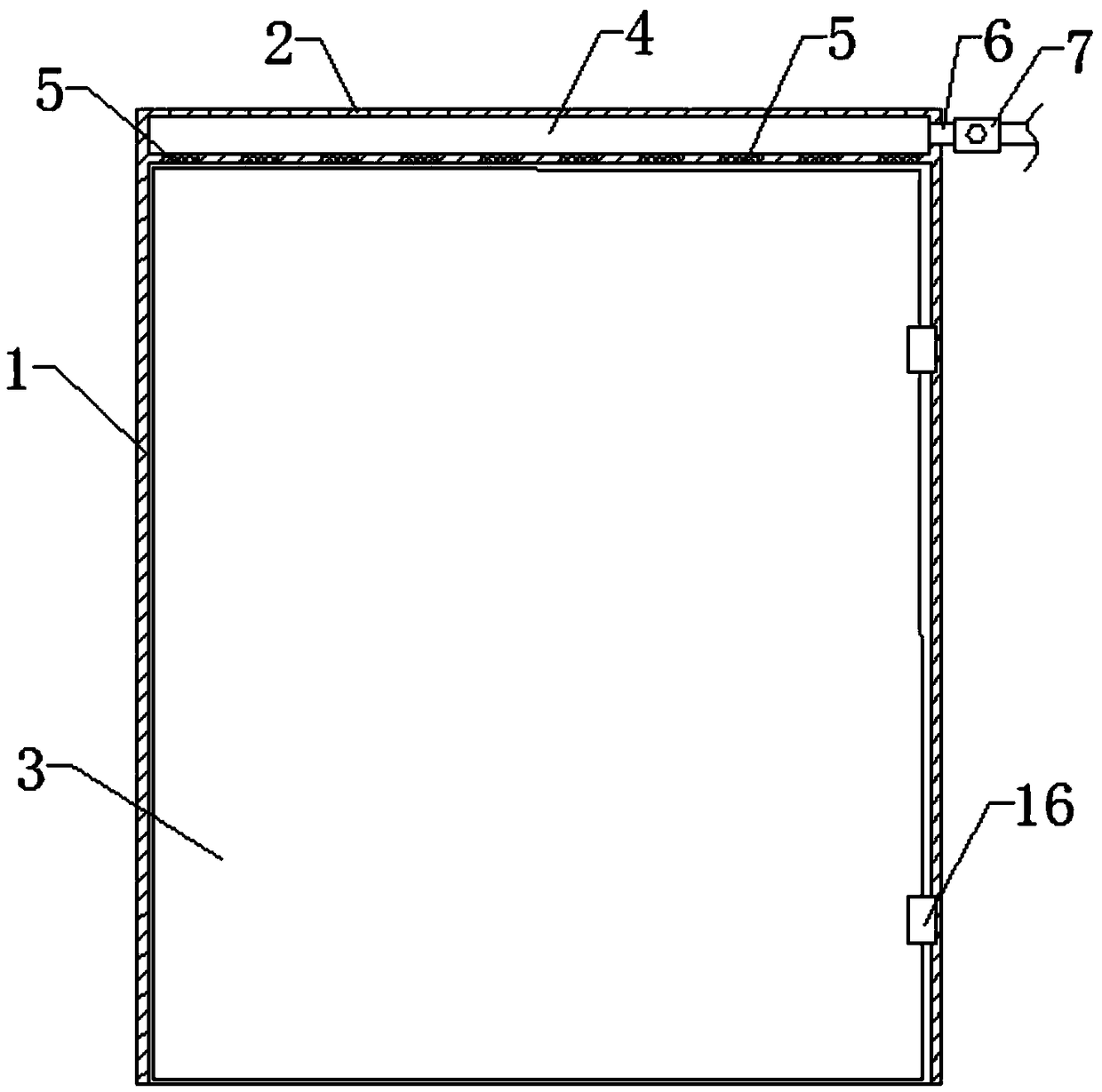
[0021] refer to figure 1 , is a schematic cross-sectional structure diagram of the first embodiment of the fire door structure; figure 2 , is the bottom view of the lintel in Embodiment 1 of the fire door structure; and image 3 , is a diagram of the operation steps of Embodiment 1 of the fire door structure.

[0022] Such as Figures 1 to 3 As shown in , the fire door structure provided by the present invention includes a door frame 1, a door lintel 2 crossed on the door frame 1, and a door body 3 hinged to one side of the door frame 1, wherein the door lintel 2 has a horizontal water storage chamber 4 inside , and the lower end surface of the lintel 2 is arranged in an array along the length direction with a number of water outlet holes 8, and each water outlet hole 8 is embedded with a plug body 5 made of PE plastic material to close the water outlet hole 8; A first water inlet pipe 6 connected to the water storage chamber 4 is installed horizontally on one side, and a ...

Embodiment 2

[0027] refer to Figure 4 , is a schematic cross-sectional structure diagram of the second embodiment of the fire door structure; Figure 5 , is a diagram of the operation steps of the second embodiment of the fire door structure. Such as Figure 4 and Figure 5 As shown in , the structure of the fire door provided in this embodiment is basically the same as that of the above-mentioned embodiment 1, the difference is that a housing chamber 3 is formed in the hollow of the door body 3, and a second Two water inlet pipes 12, and a second smoke sensor switch 11 is installed on the second water inlet pipe 12, which is used to control the channel of the second water inlet pipe 12 after detecting smoke information, and inject water into the accommodating cavity 3 to strengthen the door body 3 fire resistance.

[0028] In a preferred embodiment, the hose 10 is arranged on the side where the door body 3 is hinged to the door frame 1, and the second water inlet pipe 12 passes throu...


PUM


Abstract

The invention discloses a fireproof door structure. The fireproof door structure comprises a door frame, a lintel and a door body, wherein the lintel is transversely erected on the door frame, and thedoor body is hinged to one side of the door frame; a transverse water storage cavity is formed in the lintel, multiple water outlets in an array are formed in the lower end face of the lintel in thelength direction, and plugs made of PE plastic are embedded in all the water outlets for closing the water outlets; a first water inlet pipe communicated with the water storage cavity is horizontallymounted on one side of the lintel, a first smog sensing switch is mounted on the first water inlet pipe for controlling the first water inlet pipe to be opened or closed after detecting indoor smog information, after the indoor temperature rises to 120 DEG C or above, the plugs automatically melt and soften, the water outlets are exposed, and water flows out from the water outlets and is poured onto the door body to cool the door body, so that water mist is formed to prevent the smog from entering gaps in the periphery of the door body. By adopting the technical scheme, the door body can be cooled automatically, the smog can be prevented from entering the door, and the survival probability of people can be effectively increased when a fire comes.

Description


Claims


Application Information

Patent Timeline
Owner 唐珊珊
Learn More