A kind of tunnel top sprinkler equipment for tunnel construction

A technology for sprinkler equipment and tunnel construction, applied in tunnels, mining equipment, tunnel lining, etc., can solve problems such as water falling on workers and inconvenient sprinkler

Active Publication Date: 2020-04-07
NANTONG TAIYING NEW MATERIAL SCI & TECH CO LTD
View PDF6 Cites 0 Cited by
  • Summary
  • Abstract
  • Description
  • Claims
  • Application Information

AI Technical Summary

Problems solved by technology

[0004] In order to overcome the shortcomings of inconvenient watering and water falling on the workers in the prior art, the technical problem of the present invention is to provide a tunnel top sprinkling device for tunnel construction that is convenient for watering and prevents water from falling on the workers

Method used


Image

  • A kind of tunnel top sprinkler equipment for tunnel construction
  • A kind of tunnel top sprinkler equipment for tunnel construction
  • A kind of tunnel top sprinkler equipment for tunnel construction

Examples


Embodiment 1

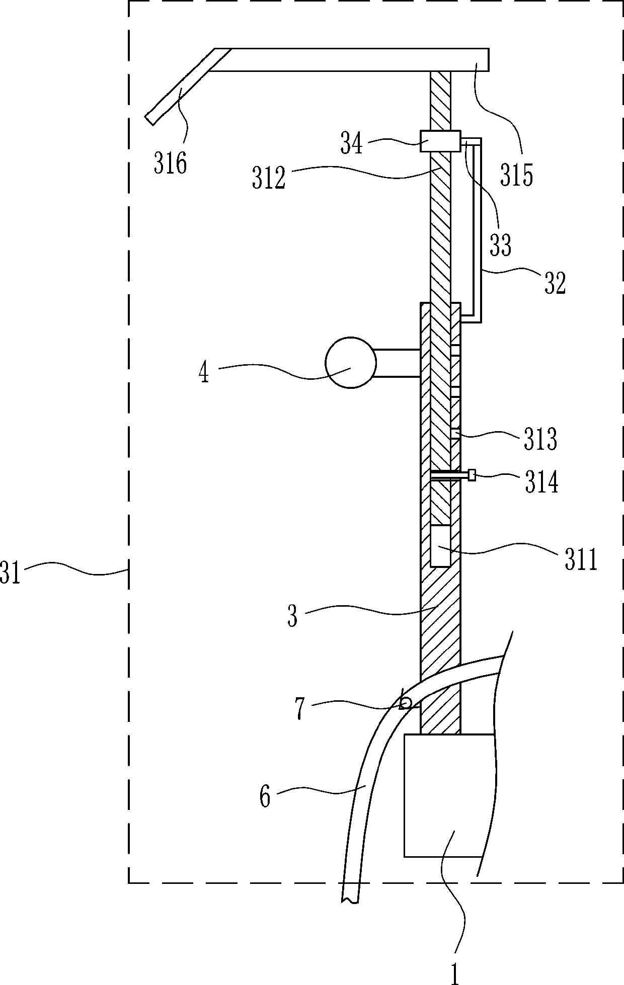
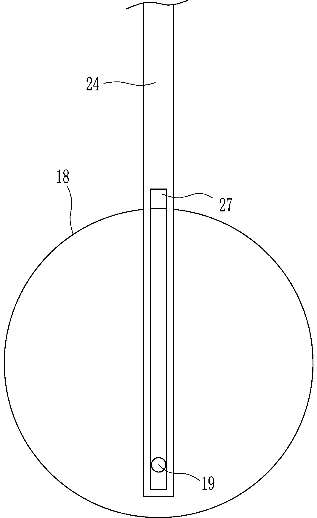
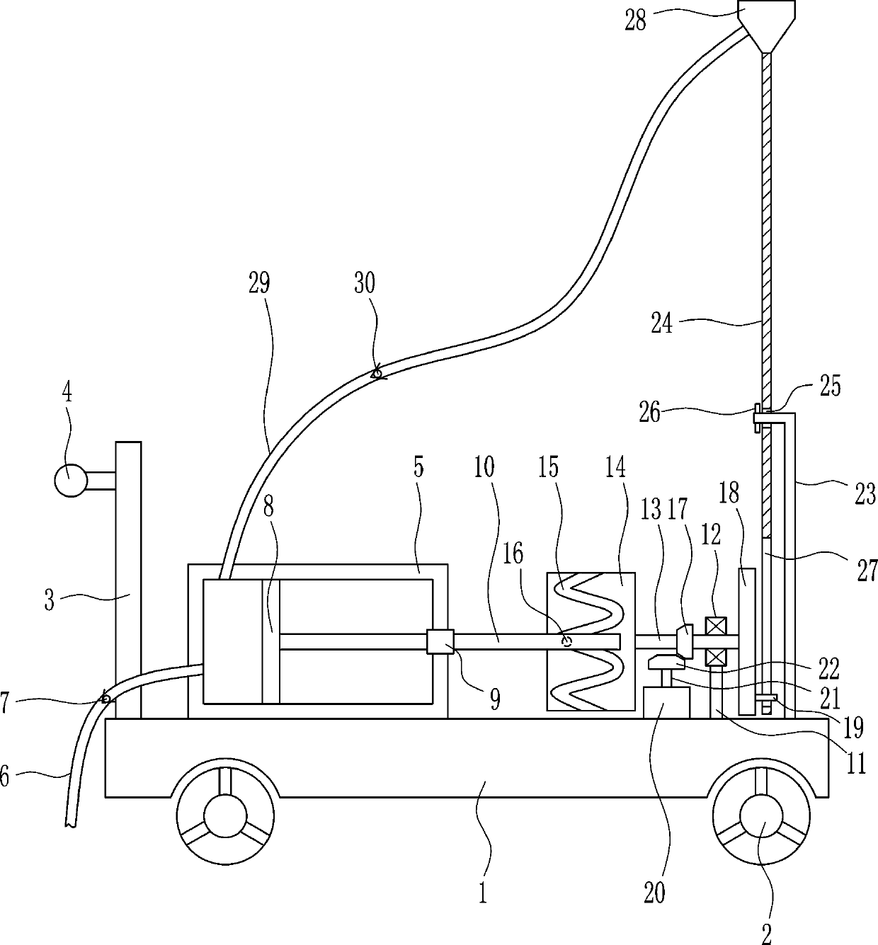
[0025] A kind of tunnel top sprinkling equipment for tunnel construction, such as Figure 1-6As shown, it includes base plate 1, wheel 2, first pole 3, push handle 4, cylinder body 5, water inlet pipe 6, first one-way valve 7, piston 8, first guide sleeve 9, push rod 10, second Strut 11, bearing housing 12, first rotating shaft 13, cylinder 14, sliding shaft 16, first bevel gear 17, disk 18, card shaft 19, motor 20, second rotating shaft 21, second bevel gear 22, L Shaped support rod 23, swing rod 24, block 26, first nozzle 28, water outlet pipe 29 and second one-way valve 30, wheels 2 are installed on the bottom of base plate 1, first support rod 3 is provided on the left side of base plate 1 top, The upper left side of the first pole 3 is provided with a push handle 4, the left side of the top of the bottom plate 1 is provided with a cylinder body 5, the cylinder body 5 is on the right side of the first pole 3, and the lower part of the left wall of the cylinder body 5 is pr...

Embodiment 2

[0027] A kind of tunnel top sprinkling equipment for tunnel construction, such as Figure 1-6 As shown, it includes base plate 1, wheel 2, first pole 3, push handle 4, cylinder body 5, water inlet pipe 6, first one-way valve 7, piston 8, first guide sleeve 9, push rod 10, second Strut 11, bearing housing 12, first rotating shaft 13, cylinder 14, sliding shaft 16, first bevel gear 17, disk 18, card shaft 19, motor 20, second rotating shaft 21, second bevel gear 22, L Shaped support rod 23, swing rod 24, block 26, first nozzle 28, water outlet pipe 29 and second one-way valve 30, wheels 2 are installed on the bottom of base plate 1, first support rod 3 is provided on the left side of base plate 1 top, The upper left side of the first pole 3 is provided with a push handle 4, the left side of the top of the bottom plate 1 is provided with a cylinder body 5, the cylinder body 5 is on the right side of the first pole 3, and the lower part of the left wall of the cylinder body 5 is p...

Embodiment 3

[0030] A kind of tunnel top sprinkling equipment for tunnel construction, such as Figure 1-6 As shown, it includes base plate 1, wheel 2, first pole 3, push handle 4, cylinder body 5, water inlet pipe 6, first one-way valve 7, piston 8, first guide sleeve 9, push rod 10, second Strut 11, bearing housing 12, first rotating shaft 13, cylinder 14, sliding shaft 16, first bevel gear 17, disk 18, card shaft 19, motor 20, second rotating shaft 21, second bevel gear 22, L Shaped support rod 23, swing rod 24, block 26, first nozzle 28, water outlet pipe 29 and second one-way valve 30, wheels 2 are installed on the bottom of base plate 1, first support rod 3 is provided on the left side of base plate 1 top, The upper left side of the first pole 3 is provided with a push handle 4, the left side of the top of the bottom plate 1 is provided with a cylinder body 5, the cylinder body 5 is on the right side of the first pole 3, and the lower part of the left wall of the cylinder body 5 is p...


PUM


Abstract

The invention relates to watering equipment, in particular to tunnel top watering equipment for tunnel construction, and aims to provide the tunnel top watering equipment for tunnel construction, wherein watering is facilitated and water does not fall on staff. The tunnel top watering equipment for tunnel construction is characterized by comprising a bottom plate, wheels, a first supporting rod, apush hand, a cylinder body, a water inlet pipe, a first one-way valve, a piston and the like; the wheels are arranged at the bottom of the bottom plate; the first supporting rod is arranged on the left side of the top of the bottom plate; the push hand is arranged on the left side of the first supporting rod; the cylinder body is arranged on the left side of the top of the bottom plate; the cylinder body is on the right side of the first supporting rod. The effects that watering is facilitated and water does not fall on the staff are achieved; the top of the tunnel can be watered only by pushing the equipment to move in the tunnel, so that watering is facilitated; a water-blocking device can block water which fall down from the top of the tunnel so as to prevent water which fall down fromthe top of the tunnel from falling on the staff.

Description

technical field [0001] The invention relates to a sprinkling device, in particular to a sprinkling device at the top of a tunnel for tunnel construction. Background technique [0002] Tunnel engineering is an underground structure, and there are various underground structures, as well as various construction methods and technologies for constructing underground structures. Construction methods and techniques form and develop in relation to the characteristics of underground structures. Its characteristic is that the vertical length is from a few meters to more than ten kilometers, and the section is relatively small, generally 5-6m high and 5-10 meters wide. The top of the tunnel is usually built with cement. After the cement is built, in order to prevent the cement from cracking, it is necessary to sprinkle water on the cement at the beginning, but because it is on the top of the tunnel, it is very inconvenient to sprinkle water, and there is still water falling. on the s...

Claims


Application Information

Patent Timeline
Patent Type & Authority Patents(China)
IPC IPC(8): E21F17/00E21D11/00
CPCE21D11/00E21F17/00
Inventor 邓志明
Owner NANTONG TAIYING NEW MATERIAL SCI & TECH CO LTD
Why Eureka
Try Eureka