
Energy collecting device of fitness equipment

A technology for energy collection and fitness equipment, which is applied to gymnastic equipment, machines/engines, mechanisms for generating mechanical power, etc., can solve the problems of inconvenient disassembly and assembly of generators, inconvenience of generator maintenance, etc. The effect of easy operation

Inactive Publication Date: 2018-11-20
边会婷
View PDF11 Cites 0 Cited by
  • Summary
  • Abstract
  • Description
  • Claims
  • Application Information

AI Technical Summary

Problems solved by technology

[0002] Nowadays people pay great attention to fitness, especially the citizens in the city often go to fitness squares and various gymnasiums for fitness. When people are doing fitness, they have done a lot of work. After retrieval, the patent No. CN102828924A patent document provides fitness energy collection The energy conversion module of the device and fitness equipment converts various kinetic energy generated by people using various fitness equipment into rotational energy. The power generation module uses the rotational energy to drive the generator to generate electricity. The energy storage module uses the storage battery to store the power generated by the generator. The lighting module connects the storage battery to various lamps for lighting. Using the matching fitness place of the present invention, a large amount of energy generated when people exercise is collected, and when lighting is needed, the energy of people’s exercise is fully utilized, energy saving and environmental protection It is beneficial to the country and the people, but the above scheme has the problem that the generator is not easy to disassemble and assemble, so it is inconvenient to maintain the generator, and the vibration of the generator does not change the buffer protection, so we propose an energy harvesting device for fitness equipment to solve the above problems

Method used


Image

  • Energy collecting device of fitness equipment
  • Energy collecting device of fitness equipment
  • Energy collecting device of fitness equipment

Examples


Embodiment

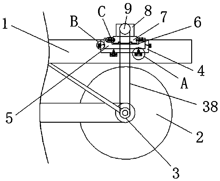
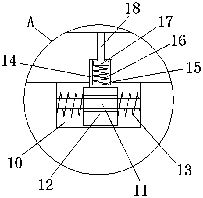
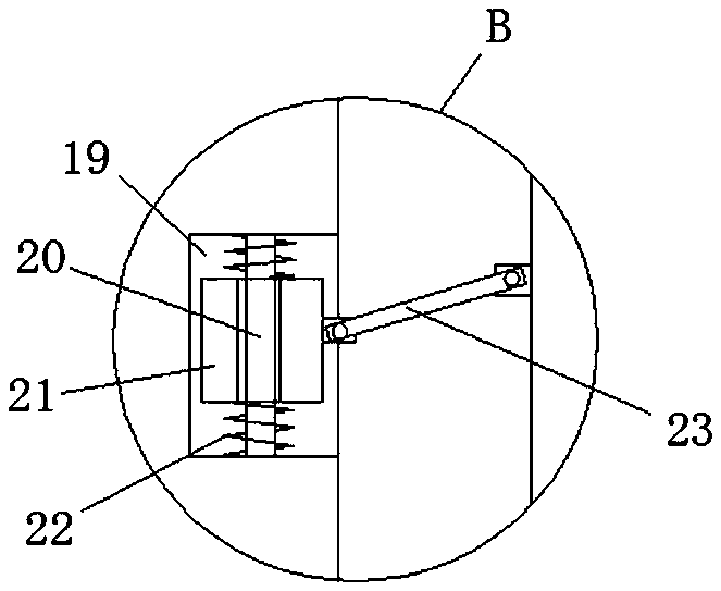
[0027] refer to Figure 1-6, a kind of energy collection device of fitness equipment is proposed in the present embodiment, comprises vehicle frame 1, and vehicle frame 1 is provided with rotating wheel 2, and one side of rotating wheel 2 is provided with first sprocket 3, and first sprocket 3 A chain 38 is engaged on the top, and the top of the vehicle frame 1 is provided with a first groove 4, and a mounting seat 5 is provided in the first groove 4, and a second groove 6 is provided on the top of the mounting seat 5, and a second groove 6 is provided in the second groove 6. A fixed block 7 is provided, and a generator 8 is fixedly installed on the top of the fixed block 7. A second sprocket 9 is welded on the output shaft of the generator 8, and the second sprocket 9 is connected to the first sprocket 3 through a chain 38. The bottom inner wall of the first groove 4 is provided with a third groove 10, and the first stabilizing rod 11 is fixedly installed on the inner walls o...


PUM


Abstract

The invention discloses an energy collecting device of fitness equipment. The device comprises a frame; a rotating wheel is arranged on the frame; a first chain wheel is arranged on one side of the rotating wheel, and is engaged with a chain; a first groove is formed in the top of the frame; a mounting base is arranged in the first groove; a second groove is formed in the top of the mounting base;a fixed block is arranged in the second groove; a generator is fixedly mounted at the top of the fixed block; a second chain wheel is welded on an output shaft of the generator, and is in transmission connection with the first chain wheel through a chain; a third groove is formed in the bottom inner wall of the first groove; first stable rods are fixedly mounted on two side inner walls of the third groove; and first slide blocks are slidingly arranged on the first stable rods in a sleeving manner. The device is high in practicability, simple in structure and convenient to operate, facilitatesbuffer protection on the generator in the vertical and horizontal directions, disassembling of the generator, maintaining of the generator and is convenient for people to use.

Description

technical field [0001] The invention relates to the technical field of fitness equipment, in particular to an energy collection device for fitness equipment. Background technique [0002] Now people pay great attention to fitness, especially the citizens in the city often go to fitness squares and various gymnasiums for fitness. When people are doing fitness, they have done a lot of work. After retrieval, the patent No. CN102828924A patent document provides fitness energy collection The energy conversion module of the device and fitness equipment converts various kinetic energy generated by people using various fitness equipment into rotational energy. The power generation module uses the rotational energy to drive the generator to generate electricity. The energy storage module uses the storage battery to store the power generated by the generator. The lighting module connects the storage battery to various lamps for lighting. Using the matching fitness place of the present...

Claims


Application Information

Patent Timeline
IPC IPC(8): F03G5/02A63B22/08
Inventor 边会婷
Owner 边会婷
Learn More