Sealing and isolating type bidirectional oil extraction pump

An oil production pump and sliding cavity technology, which is applied in the field of isolated bidirectional oil production pumps, can solve the problems of only one work, low equipment efficiency, poor economy, etc., and achieves the effects of compact structure, cost saving and simplified operation.

Inactive Publication Date: 2018-11-20
天津七盛新能源科技有限公司
View PDF0 Cites 0 Cited by
  • Summary
  • Abstract
  • Description
  • Claims
  • Application Information

AI Technical Summary

Problems solved by technology

[0002] When traditional oil production equipment is operating, it often faces the problem that it can only do work once in a stroke, which leads to low efficiency, high energy consumption, and poor economy of traditional equipment, and it cannot make good use of simple mechanical structures to achieve various production operations. , is a major bottleneck in the development of energy engineering, so there is an urgent need for a light-weight, easy-to-operate oil production pump that can perform work multiple times within the stroke, thereby simplifying costs, improving economical and power requirements, and meeting the needs of the energy mining industry. need

Method used


Image

  • Sealing and isolating type bidirectional oil extraction pump
  • Sealing and isolating type bidirectional oil extraction pump
  • Sealing and isolating type bidirectional oil extraction pump

Examples


Embodiment Construction

[0014] All features disclosed in this specification, or steps in all methods or processes disclosed, may be combined in any manner, except for mutually exclusive features and / or steps.

[0015] Any feature disclosed in this specification (including any appended claims, abstract and drawings), unless expressly stated otherwise, may be replaced by alternative features which are equivalent or serve a similar purpose. That is, unless expressly stated otherwise, each feature is one example only of a series of equivalent or similar features.

[0016] The present invention will be described in detail below in conjunction with the drawings.

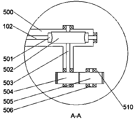
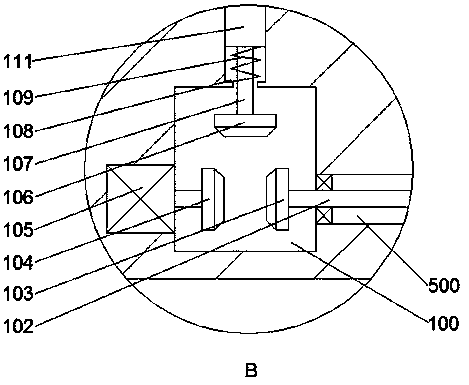
[0017] refer to Figure 1-Figure 3 As shown, a sealed bi-directional oil production pump of the present invention includes an equipment casing 101, and a traction chamber 400 is arranged inside the equipment casing. The front end surface of the disc 406 is fixed with a bump 405, the bump 405 is rotated and fitted with a first connecting rod 409...


PUM


Abstract

The invention discloses a sealing and isolating type bidirectional oil extraction pump which comprises equipment shell. A traction cavity is formed in the equipment shell. A rotating disc is installedon the inner wall of the rear side of the traction cavity in a rotating fit manner. A protruding block is fixedly arranged on the end face of the front side of the rotating disc. The protruding blockis provided with a connecting rod in a rotating fit manner. A sliding groove is formed in the left side of the traction cavity in a communicating manner. A sliding block is arranged in the sliding groove in a sliding fit manner. The sliding block and the left end of the connecting rod are matched in a rotating manner. The left side of the sliding groove is provided with a first transmission cavity in a communicating manner. A first traction wheel and a second traction wheel are installed between the front inner wall and the rear inner wall of the first transmission cavity in a rotating fit manner. The second traction wheel is located right below the first traction wheel. A first traction line is wound around the periphery of the first traction wheel. The upper end of the first traction line and the left end face of the sliding block are fixedly connected. The first traction line is wound around the periphery of the second traction wheel. A sliding cavity is formed in the right side wall of the lower portion of the first transmission cavity in a communicating manner.

Description

technical field [0001] The invention relates to the field of energy exploitation, in particular to an isolated bidirectional oil production pump. Background technique [0002] When traditional oil production equipment is operating, it often faces the problem that it can only do work once in a stroke, which leads to low efficiency, high energy consumption, and poor economy of traditional equipment, and it cannot make good use of simple mechanical structures to achieve various production operations. , is a major bottleneck in the development of energy engineering, so there is an urgent need for a light-weight, easy-to-operate oil production pump that can perform work multiple times within the stroke, thereby simplifying costs, improving economical and power requirements, and meeting the needs of the energy mining industry. need. Contents of the invention [0003] The object of the present invention is to provide an isolated bidirectional oil recovery pump, which can overcom...

Claims


Application Information

Patent Timeline
Patent Type & Authority Applications(China)
IPC IPC(8): F04C2/18F04C13/00F04C15/00E21B43/12
CPCF04C2/18E21B43/121F04C13/001F04C15/00
Inventor 马浩杰
Owner 天津七盛新能源科技有限公司
Why Eureka
Try Eureka