Supercharge Your Innovation With Domain-Expert AI Agents!

High-flux soft-stamping-type vacuum interface valve

A soft-flushing, high-throughput technology, applied to valve details, diaphragm valves, valve devices, etc., can solve the problems of inability to meet absolute sealing effect, inability to obtain speed response control, short service life, etc., and achieve convenient speed response control Reliable, simple structure and low manufacturing cost

Pending Publication Date: 2018-11-20
厚力德机器(杭州)有限公司
View PDF0 Cites 10 Cited by
  • Summary
  • Abstract
  • Description
  • Claims
  • Application Information

AI Technical Summary

Problems solved by technology

[0002] Now in the field of drainage, a stepped spool or a tapered spool is routinely used to slide inside the valve body, so as to open and close the fluid. Due to the high speed of the vacuum fluid, the conventional valve cannot obtain a more accurate speed response control at this stage, and the conventional spool Relatively moving with the valve body, they will wear each other, so the service life is relatively short, and the absolute sealing effect cannot be satisfied; in view of the problems existing in the valve, it is necessary to design a high-flux soft flush vacuum interface valve for the vacuum field. address the above deficiencies

Method used


Image

  • High-flux soft-stamping-type vacuum interface valve
  • High-flux soft-stamping-type vacuum interface valve
  • High-flux soft-stamping-type vacuum interface valve

Examples


Embodiment Construction

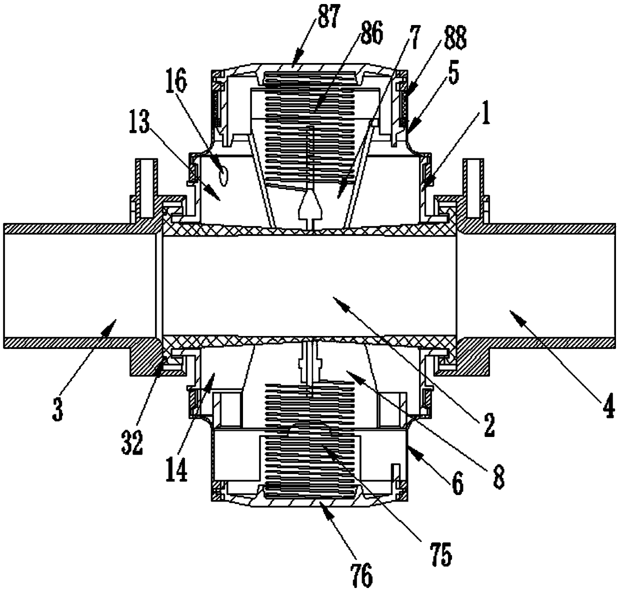
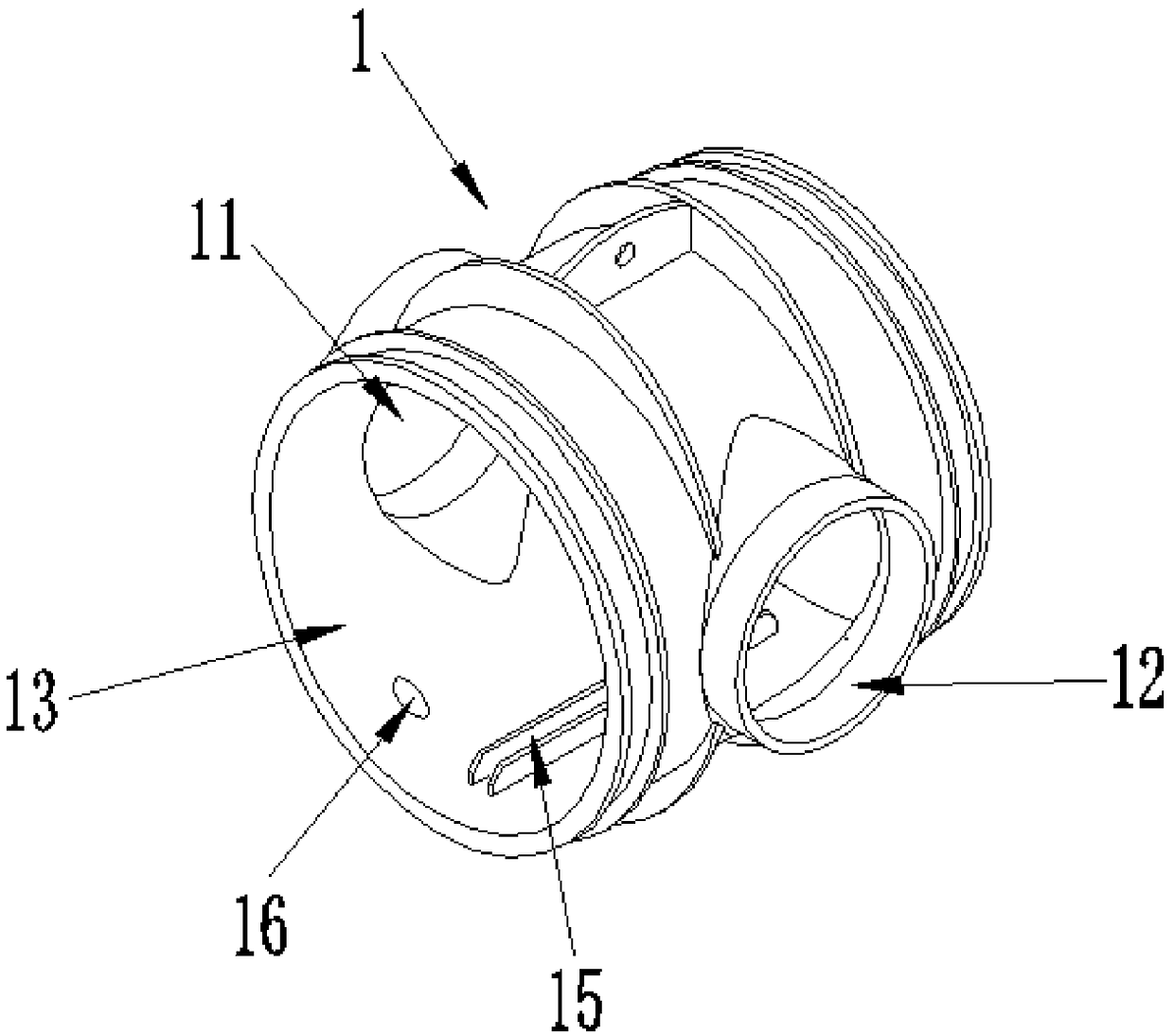
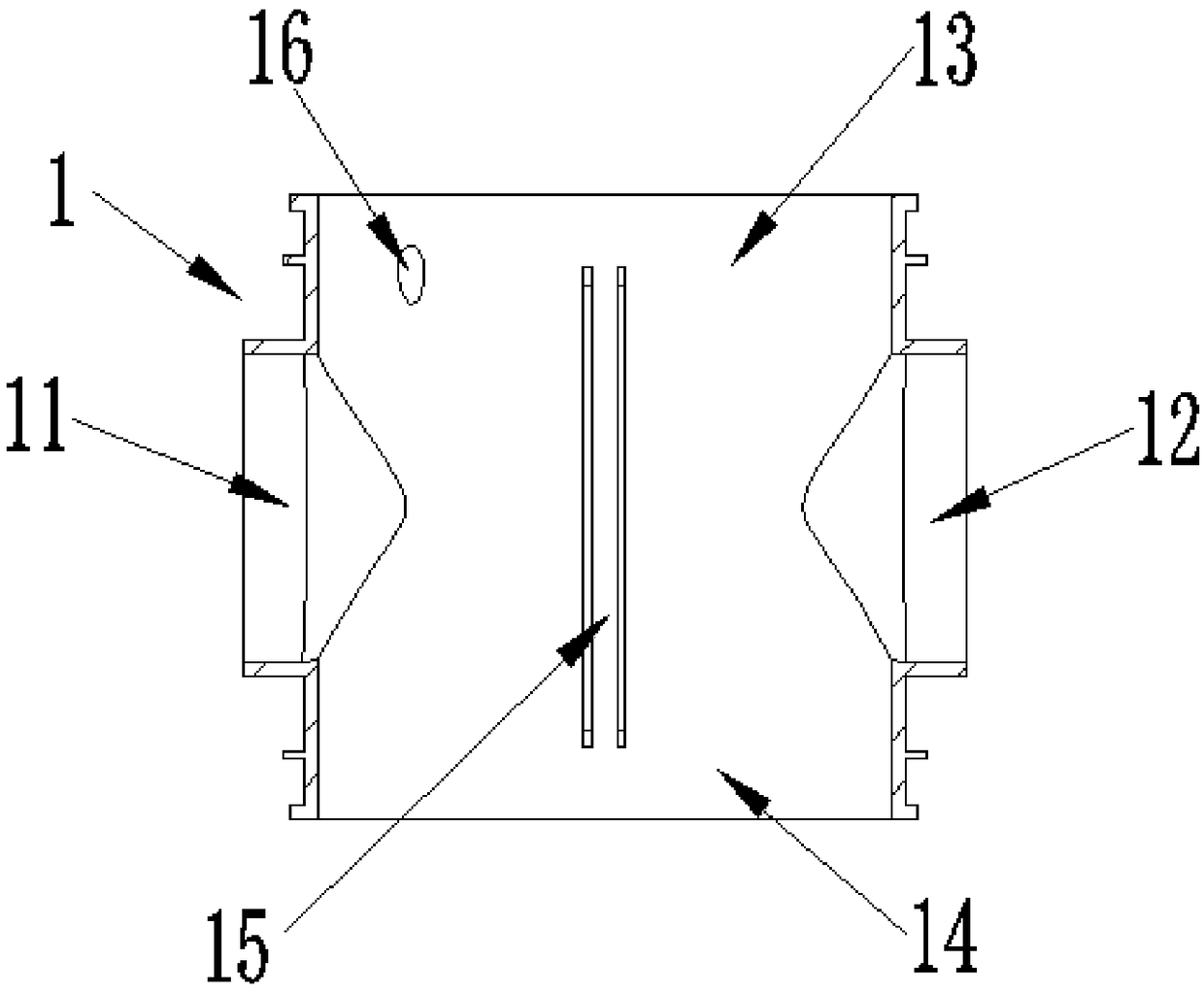
[0021] refer to Figure 1-Figure 9 , a high-throughput soft flush vacuum interface valve of the present invention, including a cross-connector 1, a hose 2, a water inlet pipe 3, a water outlet pipe 4, an upper diaphragm pressure plate 7, a lower diaphragm pressure plate 8, an upper gland 87 and a lower edge 9. A hose 2 is sleeved between the water inlet 11 and the outlet 12 of the cross 1; the outer end of the water inlet 11 of the cross 1 is provided with a water inlet 3, and the The outer end of the outlet pipe 12 is provided with a water outlet pipe 4; the cross channel 1 is provided with an upper diaphragm pressing plate 7 and a lower diaphragm pressing plate 8, and the inner sliding protrusion 82 of the lower diaphragm pressing plate 8 passes through the sliding length of the upper diaphragm pressing plate 7. In the gap 71, the upper pressure plate 72 at the lower end of the upper diaphragm pressure plate 7 and the lower pressure plate 83 of the lower diaphragm pressure p...


PUM


Abstract

The invention discloses a high-flux soft-stamping-type vacuum interface valve comprising a cross, a hose, an upper diaphragm pressing plate and a lower diaphragm pressing plate. The hose is arranged between a water inlet pipe orifice and a water outlet pipe orifice in the front portion and the rear portion of the cross in a sleeved mode. The upper diaphragm pressing plate and the lower diaphragm pressing plate are arranged in the cross; inner sliding convex strips of the lower diaphragm pressing plate are arranged in sliding long notches of the upper diaphragm pressing plate in a penetrating mode; an upper pressing plate at the lower end of the upper diaphragm pressing plate and a lower pressing plate of the lower diaphragm pressing plate are mutually staggered; an upper port and a lower port are overlapped to form a clamping port, and the hose is located in the clamping port; outer sliding convex strips of the lower diaphragm pressing plate slide in guiding rib grooves in the inner side wall of the cross; a second spring arranged in a second spring clamping groove in a sleeved mode penetrates through a circular hole in the upper end of the upper diaphragm pressing plate to jack the lower surface of an upper pressing cover, and a first spring arranged in a first spring clamping groove in a sleeved mode penetrates through a circular hole in the lower end of the lower diaphragm pressing plate to jack the inner bottom face of an lower pressing cover; and a vacuum hole is further formed in the side wall of the cross. The high-flux soft-stamping-type vacuum interface valve is low in manufacturing cost, convenient to use and capable of being widely applied and popularized.

Description

【Technical field】 [0001] The invention relates to the technical field of valves, in particular to the technical field of high-flux soft flush vacuum interface valves. 【Background technique】 [0002] Now in the field of drainage, a stepped spool or a tapered spool is routinely used to slide inside the valve body, so as to open and close the fluid. Due to the high speed of the vacuum fluid, the conventional valve cannot obtain a more accurate speed response control at this stage, and the conventional spool Relatively moving with the valve body, they will wear each other, so the service life is relatively short, and the absolute sealing effect cannot be satisfied; in view of the problems existing in the valve, it is necessary to design a high-flux soft flush vacuum interface valve for the vacuum field. address the above deficiencies. 【Content of invention】 [0003] The purpose of the present invention is to solve the problems in the prior art, and propose a high-throughput s...

Claims


Application Information

Patent Timeline
Patent Type & Authority Applications(China)
IPC IPC(8): F16K7/04F16K7/07F16K27/02F16K31/126F16K41/10
CPCF16K7/04F16K7/07F16K27/0236F16K31/1262F16K41/10
Inventor 连加俤孙富强
Owner 厚力德机器(杭州)有限公司
Features
  • R&D
  • Intellectual Property
  • Life Sciences
  • Materials
  • Tech Scout
  • Unparalleled Data Quality
  • Higher Quality Content
  • 60% Fewer Hallucinations
Learn More