Polarizer attaching and cutting integrated method and equipment for liquid crystal display panel

A liquid crystal display panel, polarizer attachment technology, applied in optics, nonlinear optics, instruments, etc., can solve the problem that the display module cannot achieve a narrow frame, and cannot eliminate the tolerance of the polarizer attached.

Inactive Publication Date: 2018-11-20
TRULY SEMICON
View PDF7 Cites 6 Cited by
  • Summary
  • Abstract
  • Description
  • Claims
  • Application Information

AI Technical Summary

Problems solved by technology

[0002] The liquid crystal display panels of the prior art usually include polarizers attached on both sides to convert natural light into linearly polarized light, and then control the optical path through the optical rotation of liquid crystal molecules. However, the existing polarizing equipment can only paste The size of the polarizer is smaller than that of the liquid crystal display panel, and the corresponding display module cannot achieve a narrow frame
[0003] The display terminal’s requirements for the design and effect without black borders are advancing day by day. The existing polarizing equipment cannot eliminate the tolerance of the polarizing plate, so the design of the polarizing plate is required to be smaller than that of the liquid crystal display panel.

Method used


Image

  • Polarizer attaching and cutting integrated method and equipment for liquid crystal display panel
  • Polarizer attaching and cutting integrated method and equipment for liquid crystal display panel
  • Polarizer attaching and cutting integrated method and equipment for liquid crystal display panel

Examples


Embodiment 1

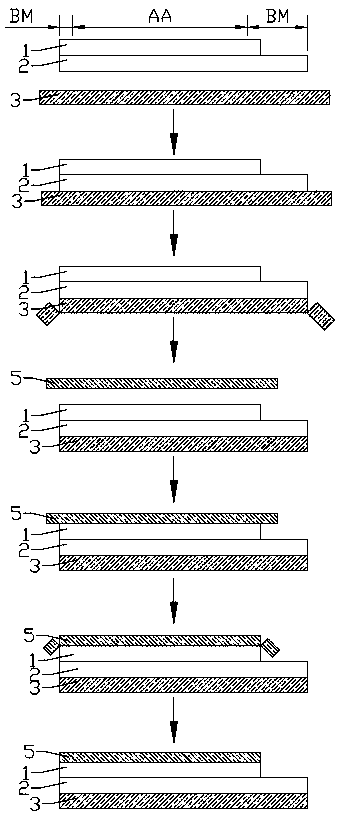
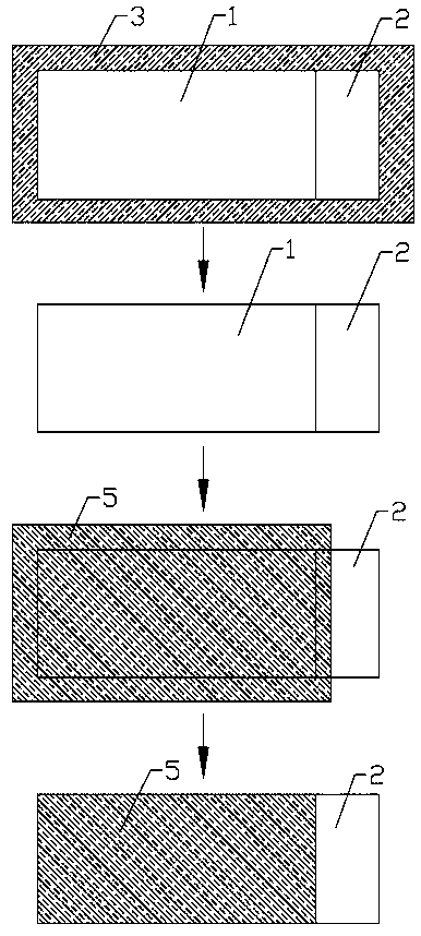
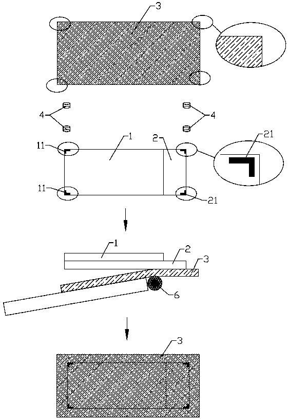
[0037] combine Figure 1-Figure 3 As shown, Embodiment 1 of the present invention provides an integrated method for attaching and cutting polarizers of a liquid crystal display panel. The liquid crystal display panel has a display area AA and a non-display area BM surrounding the periphery of the display area, including the following steps: S1: providing The upper substrate 1 and the lower substrate 2 arranged in layers, and the lower polarizer 3 whose size is larger than the lower substrate 2, the lower substrate 2 is provided with a first alignment mark 21, and the lower polarizer 3 is provided with a third pair of Position mark; S2: provide a CCD vision system 4 to take the first alignment mark 21 and the third alignment mark, attach the lower polarizer 3 on the lower substrate 2 and away from the side of the upper substrate 1; S3: use CCD The vision system 4 takes the mark on the edge of the lower substrate 2, and cuts the lower polarizer 3; S4: providing an upper polarize...

Embodiment 2

[0045] combine Figure 1-Figure 4 with Figure 8 As shown, Embodiment 2 of the present invention provides an integrated equipment for attaching and cutting polarizers for liquid crystal display panels. The structures of polarizers and liquid crystal display panels are as described in Embodiment 1, wherein the size of polarizers is larger than that of liquid crystal display panels. The liquid crystal display panel has a display area AA and a non-display area BM surrounding the periphery of the display area. The liquid crystal display panel includes an upper substrate 1 and a lower substrate 2 stacked from top to bottom, formed on the upper substrate 1 and away from the lower substrate 2. The upper polarizer 5, the lower polarizer 3 formed on the lower substrate 2 and away from the upper substrate 1, the device includes a first biasing module 100, a first cutting module 200, a second biasing module 300, a second cutting module 400 and a CCD vision system 4, the first polarizing...


PUM

PropertyMeasurementUnit
diameteraaaaaaaaaa

Abstract

The invention provides a polarizer attaching and cutting integrated method and equipment for a liquid crystal display panel. The method comprises the following steps: providing an upper substrate anda lower substrate stacked together, as well as a lower polarizer of which the size is larger than that of the lower substrate, wherein the lower substrate is provided with a first alignment mark, andthe lower polarizer is provided with a third alignment mark; providing a CCD (Charge Coupled Device) visual system, sampling the first alignment mark and the third alignment mark, and attaching the lower polarizer onto the lower substrate; sampling an edge mark of the lower substrate by utilizing the CCD visual system, and cutting the lower polarizer; providing an upper polarizer of which the sizeis larger than that of the upper substrate, wherein the upper substrate is provided with a second alignment mark, and the upper polarizer is provided with a fourth alignment mark; sampling the secondalignment mark and the fourth alignment mark by utilizing the CCD visual system, and attaching the upper polarizer onto the upper substrate; sampling the edge mark of the upper substrate by utilizingthe CCD visual system, and cutting the upper polarizer. According to the method and equipment disclosed by the invention, the requirement on the polarizer attaching and cutting accuracy is low, and the method and equipment are applicable to narrow border display.

Description

technical field [0001] The present invention relates to the technical field of display panels, in particular to a method and equipment for integrating polarizer attachment and cutting of liquid crystal display panels. Background technique [0002] The liquid crystal display panels of the prior art usually include polarizers attached on both sides to convert natural light into linearly polarized light, and then control the optical path through the optical rotation of liquid crystal molecules. However, the existing polarizing equipment can only paste The size of the polarizer is smaller than that of a liquid crystal display panel, and the corresponding display module cannot achieve a narrow frame. [0003] The display terminal's requirements for the design and effect without black borders are advancing day by day. The existing polarizing equipment cannot eliminate the tolerance of the polarizing plate, so the design of the polarizing plate is required to be smaller than that o...

Claims


Application Information

Patent Timeline
Patent Type & Authority Applications(China)
IPC IPC(8): G02F1/13G02F1/1333G02F1/1335
CPCG02F1/1303G02F1/133351G02F1/133528
Inventor 孟强赖鹏宇周洪嵩邱信红李建华
Owner TRULY SEMICON
Why Eureka
Try Eureka