
Optimized unequal-interval layout method for grounding network

An arrangement method and technology of grounding grid, which are applied in the field of electric power and can solve the problems of low stray current density, large surface potential gradient, low utilization rate of intermediate conductors, etc.

Inactive Publication Date: 2018-11-20
INST OF ECONOMIC & TECH STATE GRID HEBEI ELECTRIC POWER +1
View PDF6 Cites 1 Cited by
  • Summary
  • Abstract
  • Description
  • Claims
  • Application Information

AI Technical Summary

Problems solved by technology

The grounding grids arranged at equal intervals are shielded by the intermediate conductor, which makes the utilization rate of the intermediate conductor low and the current density of the scattered current is small, resulting in a large surface potential gradient

Method used


Image

  • Optimized unequal-interval layout method for grounding network
  • Optimized unequal-interval layout method for grounding network
  • Optimized unequal-interval layout method for grounding network

Examples


Embodiment Construction

[0033] In order to make the objectives, technical solutions and advantages of the present invention clearer, the technical solutions in the embodiments of the present invention will be described in more detail below in conjunction with the drawings in the embodiments of the present invention. In the drawings, the same or similar reference numerals denote the same or similar elements or elements having the same or similar functions throughout. The described embodiments are some, but not all, embodiments of the invention. The embodiments described below by referring to the figures are exemplary and are intended to explain the present invention and should not be construed as limiting the present invention. Based on the embodiments of the present invention, all other embodiments obtained by persons of ordinary skill in the art without creative efforts fall within the protection scope of the present invention.

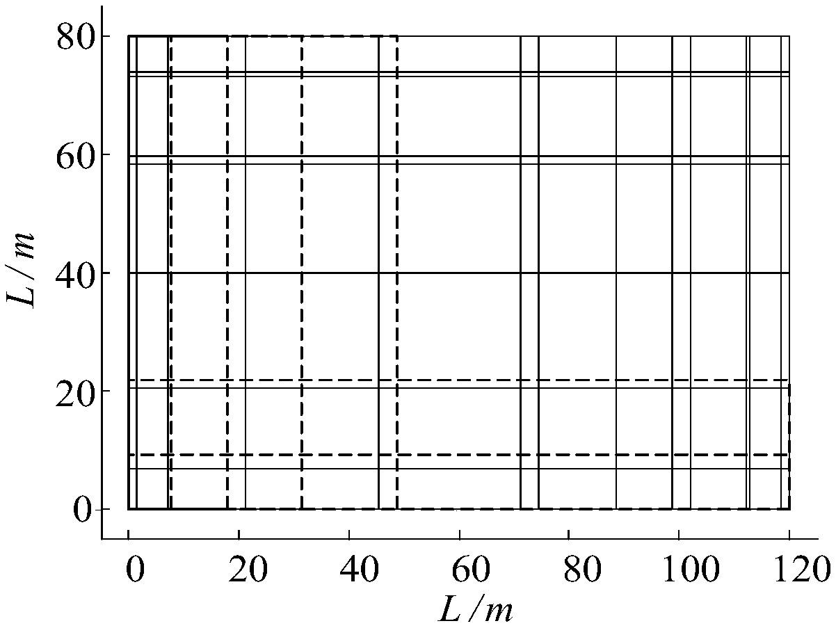
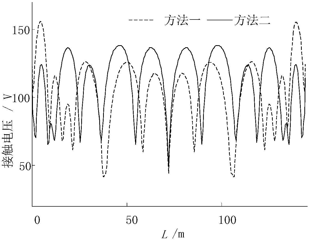
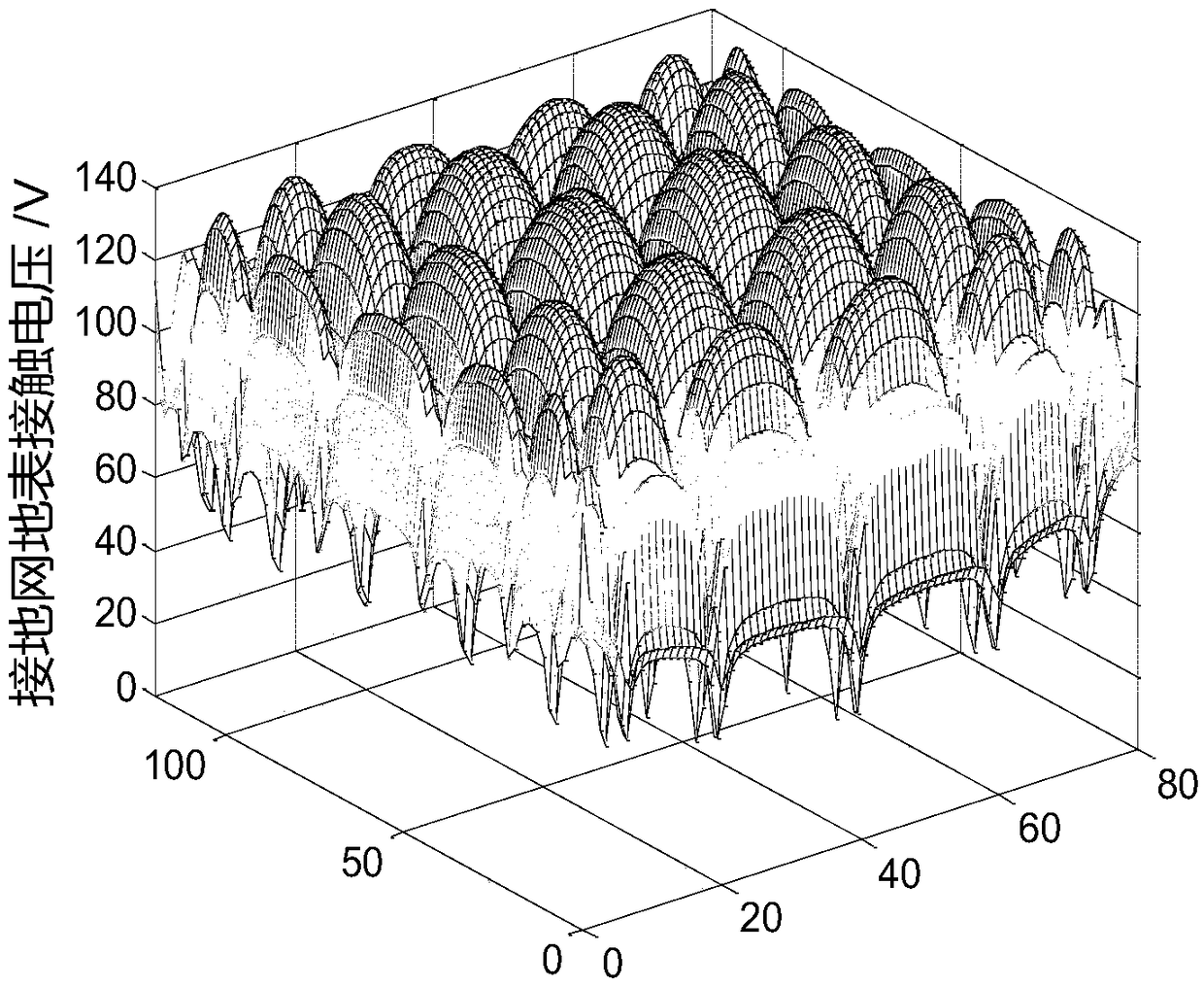
[0034] Taking a rectangular grounding grid with a length of 120m and ...


PUM


Abstract

The invention discloses an optimized unequal-interval layout method for a grounding network. The optimized unequal-interval layout method for the grounding network comprises the steps of: (1), deducing a fitting function: modelling and moving a voltage-equalizing belt by using an optimized rectangular grounding network layout scheme, so that the position of an optimized voltage-equalizing belt isobtained, and obtaining an optimization function through function fitting; (2), analyzing influence of the optimization function on the optimization coefficient in the aspects of different soil reflection coefficients, the upper soil thickness and the area of the grounding network; and (3), applying the fitting function to optimization of the rectangular grounding network under non-uniform soil.

Description

technical field [0001] The invention relates to the field of electric power technology, in particular to a method for optimal arrangement of grounding grids with unequal intervals. Background technique [0002] As the name suggests, the optimal design of the grounding grid is to adjust the position, quantity and parameters of the equalizing zone and vertical grounding body in the grounding grid to achieve a uniform potential distribution on the ground surface when the fault current leaks through the grounding grid. Each part of the grounding grid can fully play its role, reduce the ground potential gradient value, reduce the contact voltage and step voltage in the substation, and meet the relevant requirements, so as to ensure the personal safety of the staff in the substation and the normal operation of the equipment. A large number of studies have shown that when the voltage equalizing belts are evenly distributed, the contact voltage at the corners of the substation groun...

Claims


Application Information

Patent Timeline
IPC IPC(8): G06F17/50H01R43/00H01R4/66
CPCH01R4/66H01R43/00G06F30/18G06F30/20
Inventor 邢琳陈明吴景梅李慧奇吴鹏李宏博张红梅张帅王宁霍晓良李燕胡梦锦庞凝
Owner INST OF ECONOMIC & TECH STATE GRID HEBEI ELECTRIC POWER
Learn More