
Cable equipment temperature abnormity location and recognition method

An identification method and technology of equipment, applied in radiation pyrometry, character and pattern recognition, measurement devices, etc., can solve problems such as low efficiency, crowded internal environment of cable laying length, etc., achieve high accuracy, and realize abnormal location and identification. , good stability

Active Publication Date: 2018-11-20
GUANGDONG POWER GRID CO LTD +1
View PDF16 Cites 26 Cited by
  • Summary
  • Abstract
  • Description
  • Claims
  • Application Information

AI Technical Summary

Problems solved by technology

Due to the long length of cable laying and the crowded internal environment, the efficiency of manual inspection inside the cable is currently low, and it is not convenient to quickly and correctly handle abnormal cable equipment

Method used


Image

  • Cable equipment temperature abnormity location and recognition method
  • Cable equipment temperature abnormity location and recognition method

Examples


no. 1 example

[0035] This embodiment is a first embodiment of a method for locating and identifying abnormal temperature of cable equipment, including the following steps:

[0036] S1. Capture and collect sample images containing target cable equipment through the camera of the tunnel inspection robot;

[0037] S2. Expanding the sample image in step S1, generating a target number of training images and the original image together as training samples;

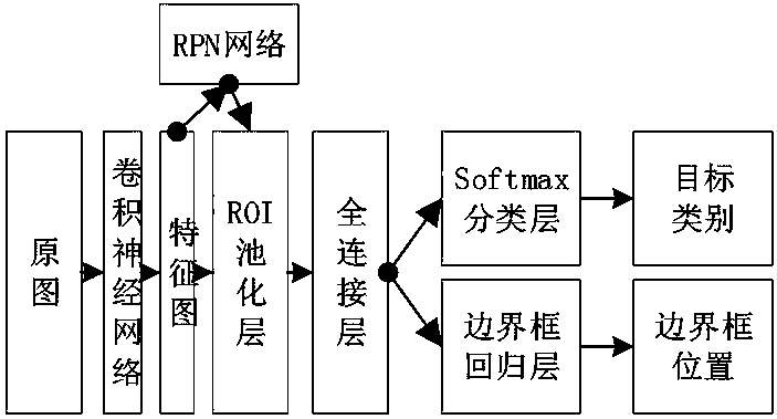
[0038] S3. Build the Faster R-CNN network model and import the training samples in step S2, initialize the RPN with the ZFNet network parameters obtained after pre-training on ImageNet, and then initialize the Faster R-CNN target detection network parameters with the pre-trained ZFNet network parameters , and extract the pre-selected area through the RPN network to train the target detection network;

[0039] S4. initialize the RPN network with the target detection network after step S3 training, fix the convolutional layer of the RPN networ...

Embodiment 2

[0061] This embodiment is the application of the method in the embodiment, collecting 250 sample images, assigning a training set and a test set to the sample images according to a ratio of 9:1, and performing cross-validation. When using the method of Embodiment 1 to detect the test pictures of the tunnel interior taken by the inspection robot, the recognition accuracy rate is above 99%, the recognition time is less than 4s, and the temperature deviation is not more than 2%. And when different cable joints appear in the test picture, according to the different angles of the captured images, the method of the present invention can also accurately detect and locate the cable joint area in the image and complete accurate result detection, so that the placement position of the camera and The vertex inspection position of the inspection robot is more free and can effectively deal with some complex environmental conditions.


PUM


Abstract

The invention relates to the technical field of computer image processing and recognition, and more specifically relates to a cable equipment temperature abnormity location and recognition method. Firstly, the training images of the target quantity are generated by expanding the samples together with the original images to act as training samples on the basis of the images taken by a cable tunnelinspection system, and the Faster R-CNN network model is constructed to train the training samples to obtain the target detection network, the position of the connector area in the visible light photograph is obtained and mapped to the infrared photograph, and the temperature of the cable connector is analyzed so as to alarm the abnormal situation in time. The invention selects to train the FasterR-CNN target detection network parameters, the RPN network is applied to extract the pre-selected area to train the target detection network, and the capacity of the convolutional neural network forextracting the two-dimensional image features is fully utilized to realize cable equipment temperature abnormity location and recognition so as to have high accuracy, wide applicability, good recognition quality and high recognition speed.

Description

technical field [0001] The present invention relates to the technical field of computer image processing and identification, and more specifically, to a method for locating and identifying abnormal temperature of cable equipment. Background technique [0002] The number of cable lines and various power equipment and communication equipment in the underground cable tunnel is gradually increasing, and the structure of the cable tunnel is more complicated due to terrain and other reasons, which makes the maintenance of underground cables more and more difficult. Due to the limitation of the technology level at the cable joint, the connection is not firm and other problems may cause the resistance at the joint to be too high. Under the thermal effect generated when the cable current flows, the cable joint will heat up, and in severe cases, the insulation of the cable will be damaged. Leakage of electricity may even cause a fire. However, thermal faults generally do not occur at...

Claims


Application Information

Patent Timeline
IPC IPC(8): G06K9/62G01J5/00
CPCG01J5/00G06F18/214G06F18/241
Inventor 仇炜黄顺涛裴星宇崔江静叶宇婷曾啸朱五洲袁永毅周小艺韦亦龙
Owner GUANGDONG POWER GRID CO LTD
Learn More