Synchronous phasor measurement configuration method for distribution network considering topology change

A topology change and configuration method technology, which is applied in the direction of circuit devices, electrical components, AC network circuits, etc., can solve problems such as the inability to guarantee the optimality of the configuration scheme of the synchrophasor measurement device, and the inability to guarantee the optimality of the solution.

Active Publication Date: 2021-04-27
TIANJIN UNIV +1
View PDF4 Cites 0 Cited by
  • Summary
  • Abstract
  • Description
  • Claims
  • Application Information

AI Technical Summary

Problems solved by technology

Although the intelligent optimization algorithm has the advantage of solution speed in some cases, it cannot guarantee the optimality of the solution, and thus cannot guarantee the optimality of the configuration scheme of the synchrophasor measurement device

Method used


Image

  • Synchronous phasor measurement configuration method for distribution network considering topology change
  • Synchronous phasor measurement configuration method for distribution network considering topology change
  • Synchronous phasor measurement configuration method for distribution network considering topology change

Examples


specific example

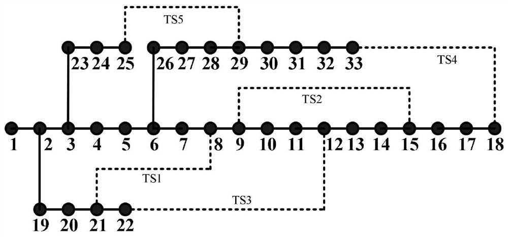
[0047] The method proposed by the present invention is verified by the IEEE 33 node calculation example, and the network topology connection relationship of the IEEE 33 node calculation example is as follows figure 2 As shown, the black dotted lines in the figure represent the tie switches TS1~TS5, and the other black solid lines represent the section switches.

[0048] In order to verify the advanced nature of the method of the present invention, the following four scenarios are taken for analysis:

[0049] Scenario 1: There is no tie switch in the network topology;

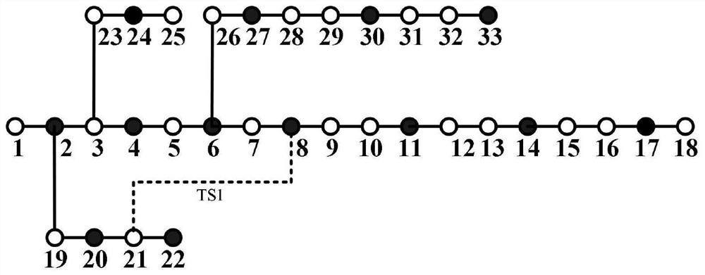
[0050] Scenario 2: There is only tie switch TS1 in the network topology;

[0051] Scenario 3: There are tie switches TS1, TS2 and TS3 in the network topology;

[0052] Scenario 4: There are all tie switches in the network topology.

[0053] The configuration scheme of Scenario 1 is shown in Table 1, and the configuration scheme of Scenario 2 is shown in Table 2. The value in the "Whether to configure" column i...


PUM


Abstract

A distribution network synchronization phasor measurement configuration method considering topology changes: obtain the topological connection relationship of the distribution network, and obtain the positions of all switches in the distribution network including tie switches and section switches; according to the topology of the distribution network Connection relationship, find out all the rings in the network when all switches are closed, determine the nodes and branches on the ring; use the nodes and branches on the ring to form a new subnetwork, calculate the degree of each node in the subnetwork, Construct a weighted incidence matrix considering the node degree of the switch; according to the weighted incidence matrix considering the node degree of the switch, construct a 0-1 integer programming model of the distribution network synchronized phasor measurement configuration considering the topology change; solve the distribution network considering the topology change The 0‑1 integer programming model of the grid synchrophasor measurement configuration is used to obtain the configuration scheme of the synchrophasor measurement device. The invention can effectively cope with the change of the switch state during the operation of the distribution network, obtain an economical and reasonable configuration scheme, and ensure the observability of the distribution system in all connection states.

Description

technical field [0001] The invention relates to a synchronization phasor measurement configuration method. In particular, it relates to a distribution network synchronized phasor measurement configuration method considering topology changes. Background technique [0002] With the continuous development and application of smart distribution network technology, the operation monitoring level of distribution network has been greatly improved. The synchronized phasor measurement device can collect the measurement data of the node voltage and branch current in the power system, realize the simultaneous measurement of the magnitude and phase angle of the quantity measurement, and compare with the traditional measurement, the accuracy is higher. Therefore, configuring a certain number of synchronized phasor measurement devices in the distribution network can further improve the measurement level of the distribution network and provide data support for the solution of distribution ...

Claims


Application Information

Patent Timeline
Patent Type & Authority Patents(China)
IPC IPC(8): H02J3/00
CPCH02J3/00H02J2203/20Y02E40/70Y02E60/00Y04S10/22
Inventor 王成山宿洪智李鹏刘喆林宋关羽赵金利于力
Owner TIANJIN UNIV
Why Eureka
Try Eureka