A fin-based ionic wind cooling device

A technology of heat dissipation device and ionized wind, which is applied to the cooling/heating device of lighting device, lighting device, cooling/ventilation/heating renovation, etc. Avoid local backflow, improve heat exchange efficiency, and increase the effect of heat dissipation area

Active Publication Date: 2019-10-11
XI AN JIAOTONG UNIV
View PDF9 Cites 0 Cited by
  • Summary
  • Abstract
  • Description
  • Claims
  • Application Information

AI Technical Summary

Problems solved by technology

[0005] 1. The application efficiency of ionic wind is low. Many ionic wind radiators dissipate heat by directly blowing the ionic wind to the hot surface. This process uses the turbulent characteristics of the ionic wind flow field to improve the heat dissipation efficiency, but the efficiency of the ionic wind itself is relatively low. Low, only about 2%, when blowing directly to the plane, the kinetic energy of the ion wind colliding with the plane will be quickly lost, making the cooling efficiency of the ion wind lower;
[0006] 2. Improper airflow circulation, a large number of ion wind cooling equipment does not consider the issue of airflow circulation, often the ion wind will blow the heated gas away from the heat source and bring it back under the action of ion wind turbulence, which greatly reduces the heat dissipation efficiency, and in many ion wind In the design of the wind radiator, the ion wind blows downward and moves upward with the hot air, and the flow between the two cancels each other out, reducing the efficiency of the ion wind;
[0007] 3. Sacrifice the heat dissipation area, apply high voltage between the ion wind electrodes to generate a strong electric field, there is a certain contradiction between the existence of a strong electric field and the dense installation of metal fins, many ion wind cooling devices give up the fins in order to use ion wind, For example, the heat dissipation effect of the ion wind on the flat plate has a high heat transfer coefficient locally, and the heat dissipation effect of the single overall cooling power is not better than that of the natural convection heat dissipation of the fins, so that the ion wind Reduced economics of cooling

Method used


Image

  • A fin-based ionic wind cooling device
  • A fin-based ionic wind cooling device
  • A fin-based ionic wind cooling device

Examples


Embodiment Construction

[0025] The present invention will be further described in detail below in conjunction with the accompanying drawings and embodiments, but it is not used as a basis for any limitation of the present invention.

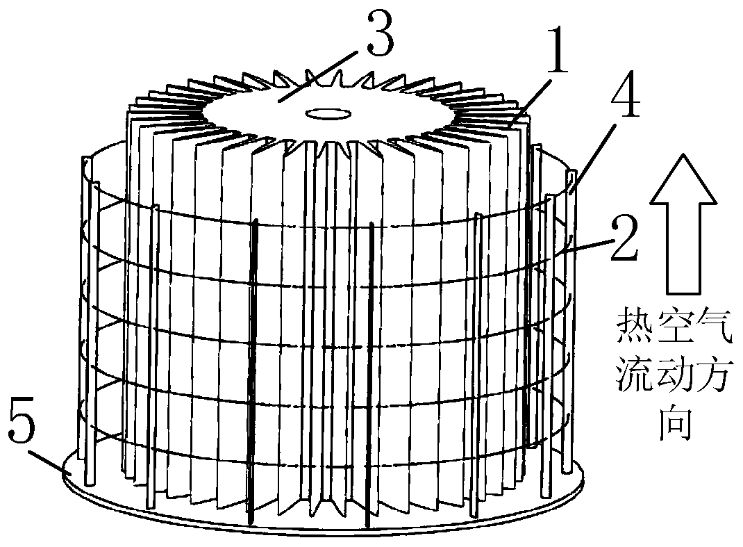
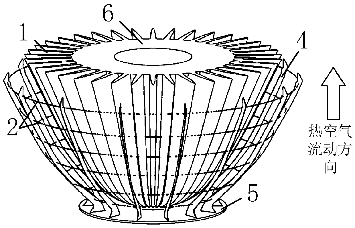
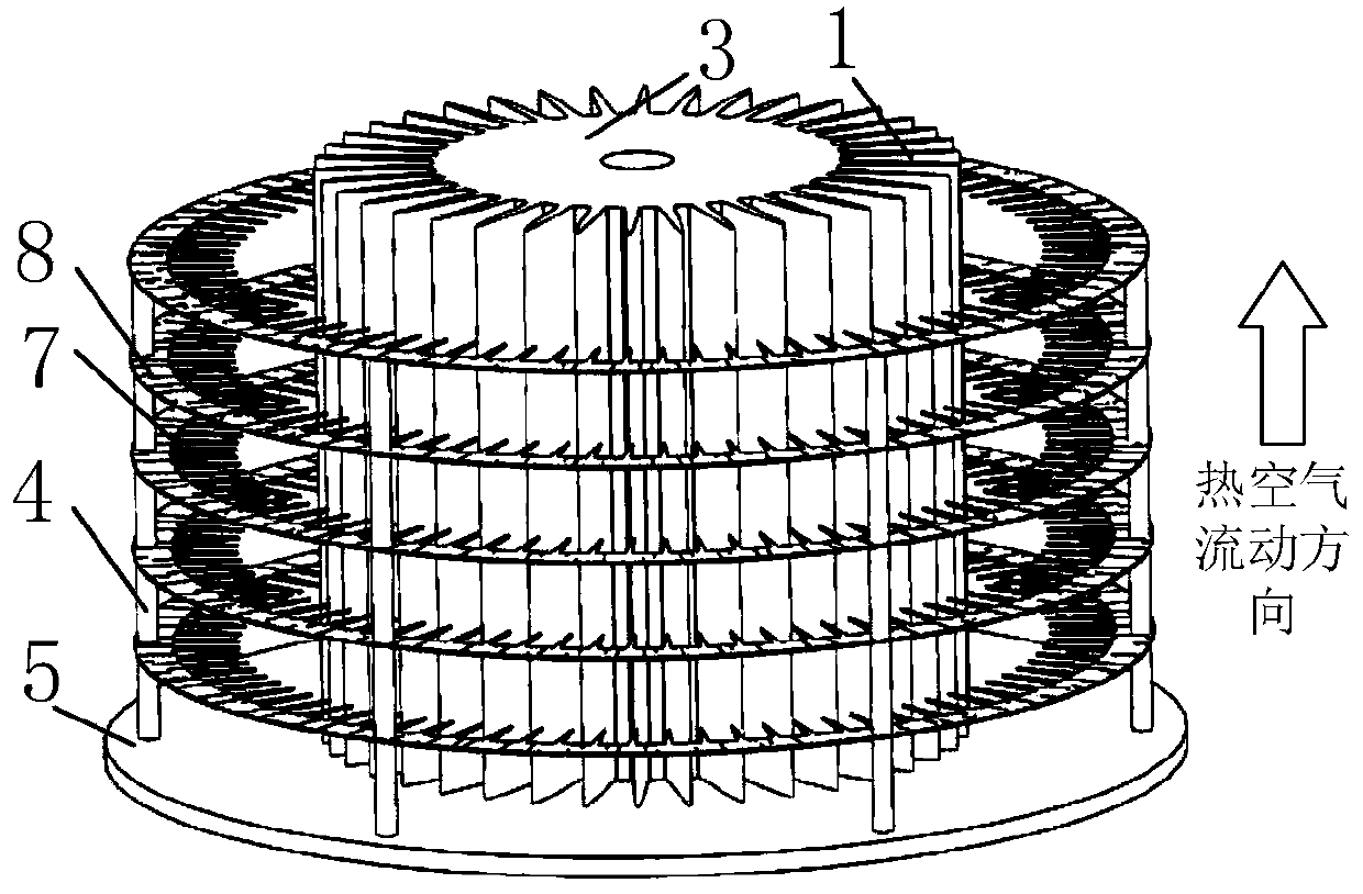
[0026] A fin-based ion wind cooling device of the present invention includes a metal radiator and an ion wind electrode, the metal radiator is provided with fins, and the outer envelope surface of the metal radiator is a rotating body; several layers of ion wind electrodes are in accordance with Equally spaced around the side of the metal radiator, and the ion wind electrode is facing the metal radiator fins; the ion wind moves from the surrounding to the metal radiator, and the air heated by the metal radiator moves from bottom to top, forming an efficient air flow mode, The phenomenon that the motions of the hot air and the air corona ion wind cancel each other out is avoided. The distance between the fins of the metal radiator is less than 1 / 3 of the distance from th...


PUM


Abstract

The invention discloses a rib-based ion wind cooling device. The rib-based ion wind cooling device comprises a cooling heat sink and ion wind electrodes, wherein ribs are arranged on the metal heat sink, an external enveloping surface of the metal heat sink is a rotation body, a side surface of the metal heat sink is encircled by a plurality of layers of ion wind electrodes at equal distance, surface electric field effect is formed among the ribs of the heat sink by applying a high voltage between the ion wind electrodes and the metal heat sink, so that ion wind cooling is achieved. The distance among the ribs on the surfaces of the metal heat sink is relatively small, an electric field effect similar to a smooth metal surface is formed, the cooling area is expanded, meanwhile, the kineticenergy loss of ionic wind directly blowing a planar electrode is prevented, and the ion wind forced cooling power and efficiency are improved. Comapred with a traditional ion wind cooling device, therib-based ion wind cooling device has the advantages that ion wind directly blows the ribs, the cooling area is expanded, and the heat exchange efficiency is high by cooperation of hot air flowing and ion flow flowing direction.

Description

technical field [0001] The invention belongs to the field of radiators, and in particular relates to a radiator product that utilizes ion wind to enhance heat dissipation. Background technique [0002] The pursuit of miniaturization of electronic products often brings about more difficult problems of heat dissipation, and the quality of heat dissipation has become an important factor restricting the life of electronic products. The traditional heat dissipation technology using fans combined with fins has problems such as high noise, high failure rate, and difficult application in outdoor environments, and the angle of wind generated by fans is very limited. However, the method of only using fins to dissipate heat is not suitable for occasions with high heat flux density, so it is very important to develop new heat dissipation technologies. Taking LED as an example, generally speaking, high-brightness LED lamps currently on the market often use natural heat dissipation to di...

Claims


Application Information

Patent Timeline
Patent Type & Authority Patents(China)
IPC IPC(8): H05K7/20F21V29/63F21V29/77F21Y115/10
Inventor 杨兰均张立韩佳一郭胜辉喻梦晗詹唯史宇昊
Owner XI AN JIAOTONG UNIV
Why Eureka
Try Eureka