
Purging assembly and spray nozzle thereof

A technology for nozzles and components, applied in the field of purge components and their nozzles, which can solve the problems of easy wear and durability of nozzles, and achieve the effects of reducing replacement, increasing wear resistance, and enhancing wear resistance

Active Publication Date: 2018-11-23
中石油吉林化工工程有限公司
View PDF6 Cites 0 Cited by
  • Summary
  • Abstract
  • Description
  • Claims
  • Application Information

AI Technical Summary

Problems solved by technology

[0003] The purpose of the present invention is to provide a purge assembly and its nozzle, which can improve the problem that the nozzle is easy to wear and not durable

Method used


Image

  • Purging assembly and spray nozzle thereof
  • Purging assembly and spray nozzle thereof
  • Purging assembly and spray nozzle thereof

Examples


Embodiment Construction

[0025] In order to more clearly describe the embodiments of the present invention or the technical solutions in the prior art, the following will briefly introduce the drawings that are used in the embodiments. Apparently, the drawings in the following description are only some embodiments of the present invention, and those skilled in the art can also obtain other drawings according to these drawings without creative efforts.

[0026] When describing the embodiments of the present invention, the terms "vertical", "transverse", "upper", "lower", "front", "rear", "left", "right", "vertical", " The orientation or positional relationship expressed by "horizontal", "top", "bottom", "inner" and "outer" is based on the orientation or positional relationship shown in the relevant drawings, which are only for the convenience of describing the present invention and simplifying the description, and It is not to indicate or imply that the device or element referred to must have a particu...


PUM


Abstract

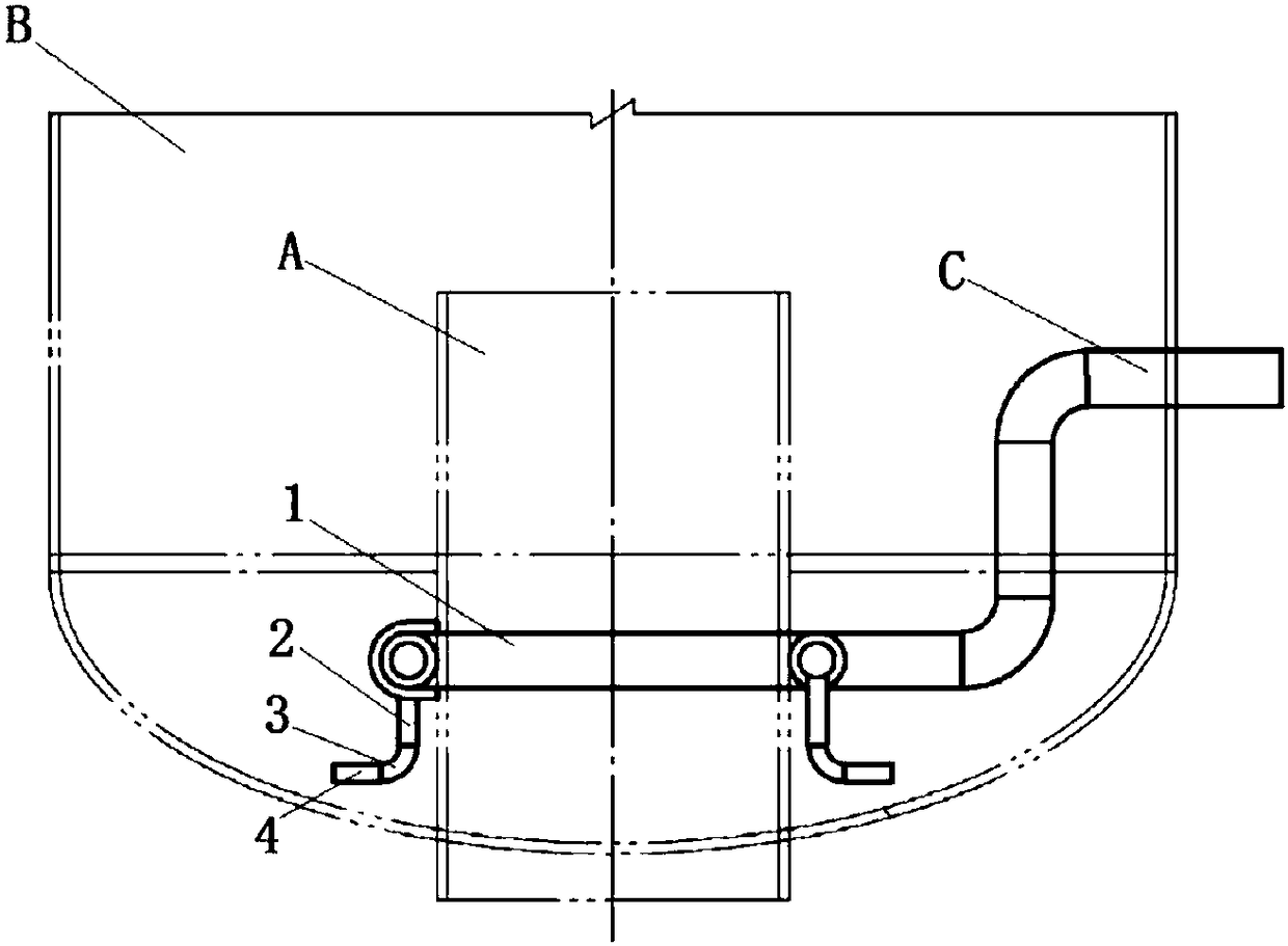
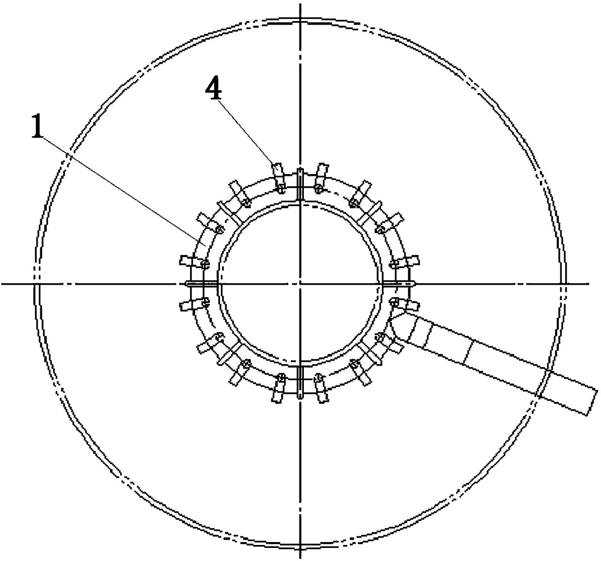
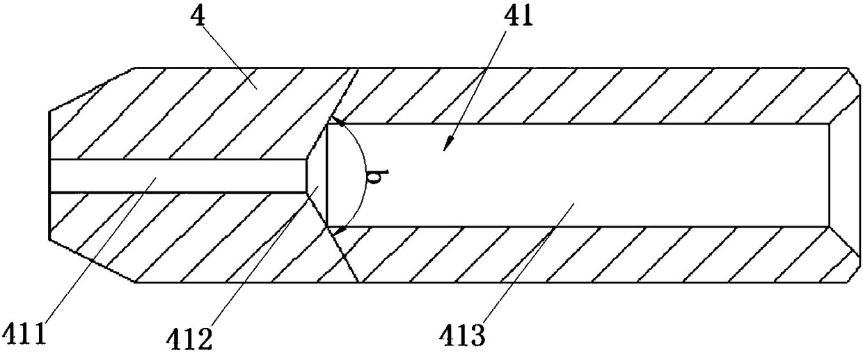
The invention relates to a purging assembly and a spray nozzle thereof. The purging assembly comprises an annular pipe, branch pipes, elbows and the spray nozzles, wherein the two ends of each of thebranch pipes are connected with one annular pipe and the corresponding elbow separately; the spray nozzles are connected with the elbows; the purging assembly is characterized in that the branch pipesare uniformly distributed along the annular pipe; the branch pipes are perpendicular to the plane of the annular pipe; the end, connected with the corresponding elbow, of each of the branch pipes, ispositioned below the plane of the annular pipe; the diameter of a circle of one end, far away from each of the elbows, of the corresponding spray nozzle is greater than the diameter of the annular pipe; and the central included angles of adjacent spray nozzles are equal. The purging assembly adopts the spray nozzles which are integrally thickened, so that replacement of the spray nozzles of the entire purging assembly is reduced, the service life of the entire purging assembly is prolonged, and the entire purging assembly is durable in use.

Description

technical field [0001] The invention relates to a purging component and its nozzle. Background technique [0002] In the catalyst distributor, part of the catalyst falls to the bottom of the distributor during the sinking process of the catalyst along the wall. If it is not cleaned in time, the catalyst will accumulate and the catalyst activity will gradually disappear. The catalyst particles are blown up again, and then flow into the reaction area along the distribution pipe on the wall of the device. In the prior art, the nozzle of the catalyst purge assembly is a steel pipe that is flattened into a "duckbill" structure, and the catalyst in the distributor is severely abrasive to the nozzle. , causing the nozzles pressed by steel pipes to be easily worn, resulting in a reduction in the life of the nozzles, requiring frequent replacement and maintenance, which increases the cost. Contents of the invention [0003] The object of the present invention is to provide a purge...

Claims


Application Information

Patent Timeline
Patent Type & Authority Applications(China)
IPC IPC(8): B05B1/02B08B5/02
CPCB05B1/02B08B5/02
Inventor 高合龙刘锦旗倪云峰邓国锋朴玄浩王献武宋顺利王宏丽代国兴乔世洪
Owner 中石油吉林化工工程有限公司
Learn More