Cleaning device for valves

A technology for cleaning devices and valves, which is applied to the cleaning method using liquid, the cleaning method using gas flow, and the arrangement of dry gas, etc., can solve the problems of difficulty in meeting the needs of large-scale valve production, unclean cleaning, and high labor intensity. Conducive to cleaning, better effect, lower labor intensity

Inactive Publication Date: 2018-11-23
WUHU JIENUO TECH
View PDF7 Cites 0 Cited by
  • Summary
  • Abstract
  • Description
  • Claims
  • Application Information

AI Technical Summary

Problems solved by technology

[0003] At present, the cleaning of the valve is mostly done manually, and it is directly placed in a large-scale cleaning equipment for cleaning and then taken out. At some corners, the cleaning is not clean, and the manual operation is labor-intensive, time-consuming and inefficient, which makes it difficult to meet the production demand for large-scale valves

Method used


Image

  • Cleaning device for valves
  • Cleaning device for valves

Examples


Embodiment Construction

[0017] In order to make the technical means, creative features, goals and effects achieved by the present invention easy to understand, the present invention will be further elaborated below.

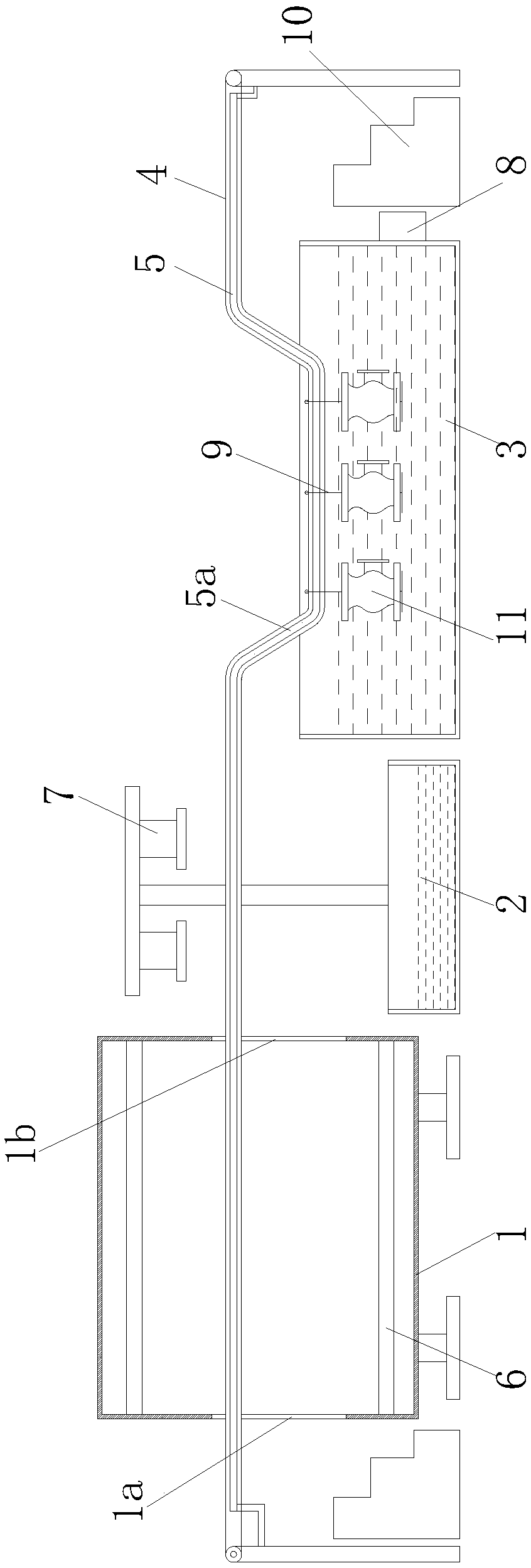
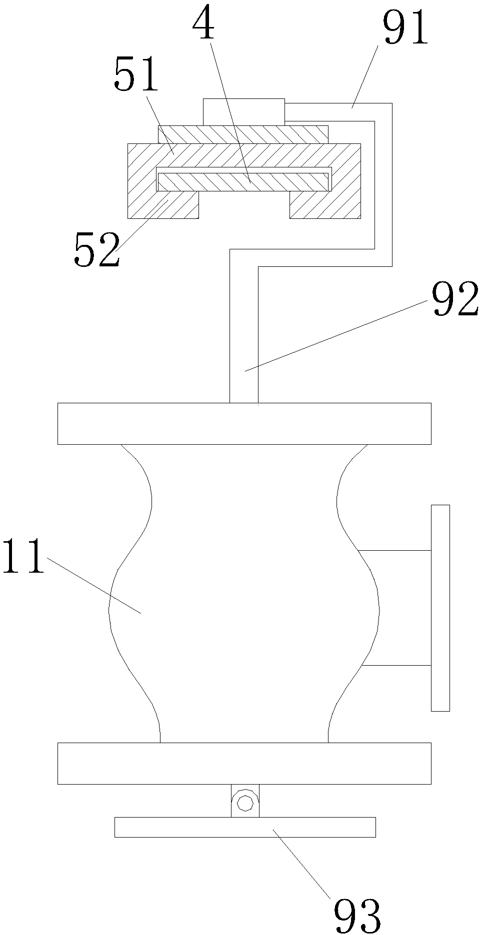
[0018] Such as Figure 1 to Figure 2 As shown, a valve cleaning device includes a drying box 1, a water storage tank 2, and a cleaning box 3 arranged sequentially from left to right; Line 4, a support guide plate 5 is provided between the upper and lower chains of the chain conveying line 4, and an inverted trapezoidal guide portion 5a is provided at the corresponding position of the support guide plate 5 and the cleaning box 3. When in use, the inverted trapezoidal guide part 5a facilitates sinking the valve 11 on the chain conveying line 4 into the cleaning box 3, which is efficient and fast.

[0019] The upper and lower walls of the drying box 1 are fixed with heating rods 6, and the upper end of the water storage tank 2 is provided with several air blowers 7 arranged in rows with t...


PUM


Abstract

The invention relates to a cleaning device for valves. The cleaning device comprises a drying case, a water storage tank, a cleaning tank and a chain conveyor line, wherein the drying case, the waterstorage tank and the cleaning tank are arranged in sequence from left to right, and the chain conveyor line is arranged above the drying case, the water storage tank and the cleaning tank. A supporting guide plate is arranged between upper and lower chains of the chain conveyor line, an inverted trapezoidal guide portion is arranged at the corresponding position of the supporting guide plate and the cleaning tank, and heating bars are fixed to the upper and lower walls of the drying case. A plurality of air blowers arranged in rows and with air openings vertically downward are arranged at theupper end of the water storage tank, an ultrasonic oscillator is installed on the cleaning tank, and a plurality of hooks for fixing the valves are uniformly distributed on the chain conveyor line. According to the cleaning device for the valves, automatic operation of cleaning and drying of the valves is realized by combining a chine plate conveying line, the demand that the valves are cleaned inbatch can be realized, the labor intensity is reduced, the working efficiency is improved, internal cleaning and drying are facilitated better, and the effect is better.

Description

technical field [0001] The invention relates to the technical field of valve cleaning, in particular to a valve cleaning device. Background technique [0002] When the valve is molded and manufactured, it needs to go through multiple processes such as milling, drilling, grinding, and painting. This process will generate a lot of waste or dust, which is difficult to remove. Especially in the spraying process, whether the valve is cleaned is also important. It determines the quality of the spray film on the surface of the valve, which in turn affects the service life of the valve. It can be seen that valve cleaning is particularly important in the process of valve processing. [0003] At present, the cleaning of the valve is mostly done manually, and it is directly placed in a large-scale cleaning equipment for cleaning and then taken out. In some corners, the cleaning is not clean, and the manual operation is labor-intensive, time-consuming and inefficient, which makes it di...

Claims


Application Information

Patent Timeline
IPC IPC(8): B08B3/12B08B5/02B08B13/00F26B21/00F26B15/04
CPCB08B3/12B08B3/123B08B5/023B08B13/00F26B15/04F26B21/00
Inventor 鲁明鲁传玉鲁俊
Owner WUHU JIENUO TECH
Why Eureka
Try Eureka