
Steel billet receiving bench

A material table and billet technology, applied in the field of iron and steel equipment, can solve the problems of deformation of the receiving plate, increase the use cost, and easily damage the internal structure of the tire frame, and achieve the effect of realizing energy conversion, reducing energy consumption and saving maintenance costs.

Pending Publication Date: 2018-11-23
ZHEJIANG OCEAN UNIV
View PDF7 Cites 0 Cited by
  • Summary
  • Abstract
  • Description
  • Claims
  • Application Information

AI Technical Summary

Problems solved by technology

[0002] In the initial stage of the production line of the section steel rolling mill, the crane transports the steel billet to the top of the receiving tire frame, and then releases the steel billet, and the steel billet falls on the receiving tire frame. distance, and the existing tire frame is a rigid structure, the steel billet will have a huge impact on the tire frame, the impact will deform the material receiving plate on the tire frame, and the long-term impact will easily damage the internal structure of the tire frame, shorten the shelf life
[0003] In addition, since the surface of the receiving plate becomes uneven, the friction force of the pusher to push the billet is increased, and the energy consumption of the pusher is increased. Therefore, it is necessary to replace the damaged receiving plate in time. Due to the existing material receiving The boards are integral and need to be replaced as a whole, which increases the cost of use

Method used


Image

  • Steel billet receiving bench
  • Steel billet receiving bench
  • Steel billet receiving bench

Examples


Embodiment Construction

[0031] The following are specific embodiments of the present invention and in conjunction with the accompanying drawings, the technical solutions of the present invention are further described, but the present invention is not limited to these embodiments.

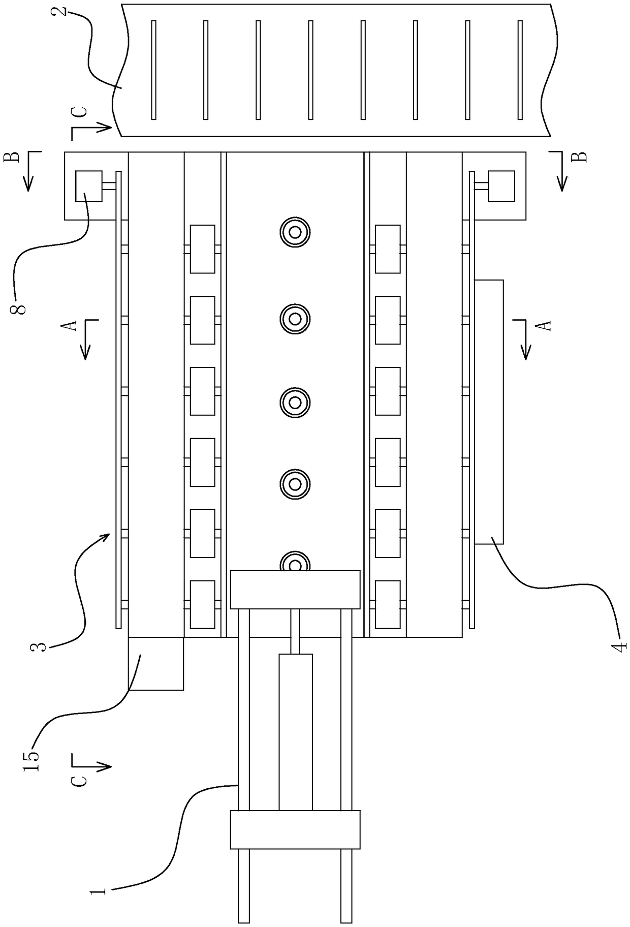
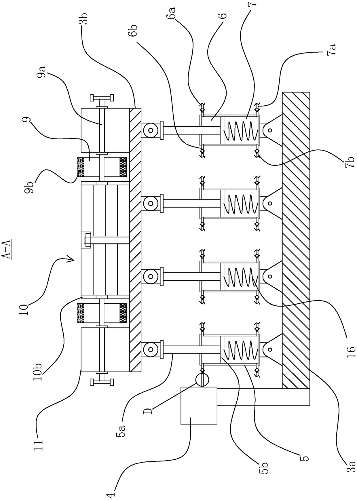
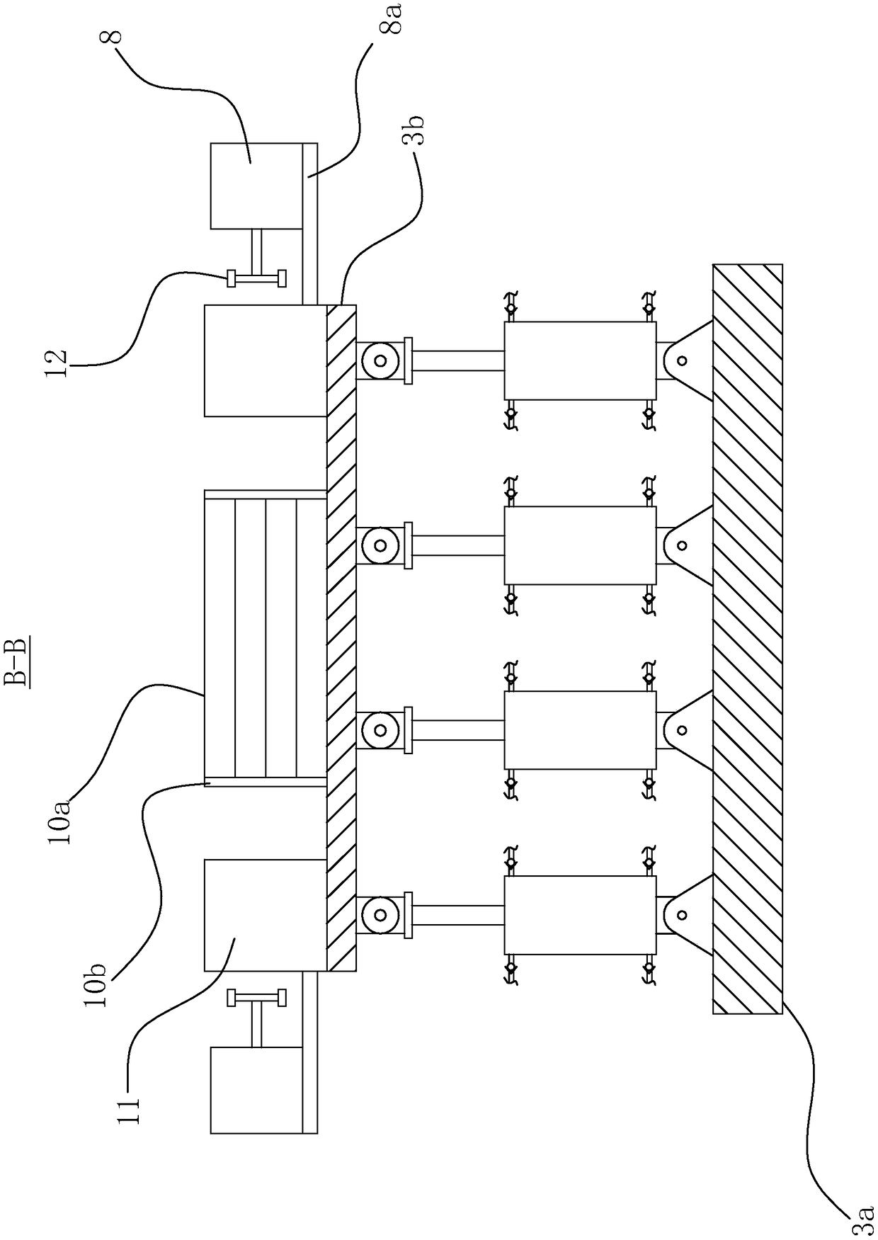
[0032] like Figures 1 to 5As shown, a steel billet receiving platform includes a tire frame body 3, and the tire frame body 3 includes an upper base 3b and a lower base 3a, and the upper side of the upper base 3b is provided with a material receiving block 10 and two support bases 11, the two support bases 11 are respectively located on the left and right sides of the upper base 3b, the upper side of the support base 11 is flush with the upper side of the receiving block 10, and the receiving block 10 Several rotating shafts 9a are rotated between the left side of the upper base 3b and the support base 11 on the left side of the upper base 3b, and a number of rotating shafts 9a are also rotated between the right side of t...


PUM


Abstract

The invention provides a steel billet receiving bench, and belongs to the technical field of steel equipment. The bench comprises a bed-jig body which comprises an upper base and a lower base, the upper end surface of the upper base is provided with a receiving block and two support seats, the two support seats are respectively located on the left and right sides of the upper base, a plurality ofrotating shafts are arranged between the left side of the receiving block and the support seat on the left side of the upper base, a plurality of rotating shafts are also rotatably arranged between the right side of the receiving block and the support seat on the right side of the upper base, the rotating shafts are provided with rollers, the rotating shafts are disposed at the ends of the supportseats and protrude from the support seats, the end portions are provided with first power generating devices capable of generating electricity by rotating the rotating shafts, and a piston device capable of reducing the impact of a steel billet on the bed-jig body when the steel billet is dropped onto the receiving block is arranged between the lower side surface of the upper base and the upper side surface of the lower base. The bench has the advantages of impact resistance, convenient maintenance and the like, can convert kinetic energy into electric energy during the process of pushing steel, and is energy-saving and environmentally friendly.

Description

technical field [0001] The invention belongs to the technical field of iron and steel equipment, and relates to a billet receiving platform. Background technique [0002] In the initial stage of the production line of the section steel rolling mill, the crane transports the steel billet to the top of the material receiving frame, and then releases the steel billet, and the steel billet falls on the material receiving frame, because there is a certain distance between the steel billet and the tire frame before falling distance, and the existing tire frame is a rigid structure, the steel blank will have a huge impact on the tire frame, and the impact will deform the receiving plate on the tire frame, and the long-term impact will easily damage the internal structure of the tire frame and shorten the tire shelf life. [0003] In addition, since the surface of the receiving plate becomes uneven, the friction force of the pusher to push the billet is increased, and the energy co...

Claims


Application Information

Patent Timeline
Patent Type & Authority Applications(China)
IPC IPC(8): B21B39/04
CPCB21B39/04
Inventor 尹佳乐史晓敏
Owner ZHEJIANG OCEAN UNIV
Learn More