Pipe orifice machining device and machining method thereof

A processing device and processing method technology, applied in the field of flanging processing device, stainless steel pipe nozzle shrinkage, can solve problems such as easy to produce water leakage, affect product life and cost, unable to shrink and deform, avoid heat, prevent overheating and burning bad effect

Pending Publication Date: 2018-11-23
KAIPING QILONG SANITARY WARE TECH CO LTD
View PDF0 Cites 2 Cited by
  • Summary
  • Abstract
  • Description
  • Claims
  • Application Information

AI Technical Summary

Problems solved by technology

[0002] At present, in the nozzle shrinking of sanitary stainless steel water pipes, forming tools are often used to hard compress tubes, that is, the nozzles to be processed are rotated and extruded by a tool with a fixed contour shape to shrink the nozzles, but this process is only suitable for applications. On metals that are relatively soft and thin and easy to be squeezed and deformed, especially stainless steel pipes with a certain thickness cannot shrink and deform at all. However, various water leakage problems have appeared in thin tube products in practical applications, which affects the life and cost of the product; therefore, it is urgent to study a device that can also shrink and flang the nozzle of a stainless steel tube with a certain thickness. method, so that stainless steel pipes with increased thickness can be processed and put into use, and fundamentally solve the problem of water leakage that can only be caused by using thin stainless steel pipes

Method used


Image

  • Pipe orifice machining device and machining method thereof
  • Pipe orifice machining device and machining method thereof
  • Pipe orifice machining device and machining method thereof

Examples


Embodiment Construction

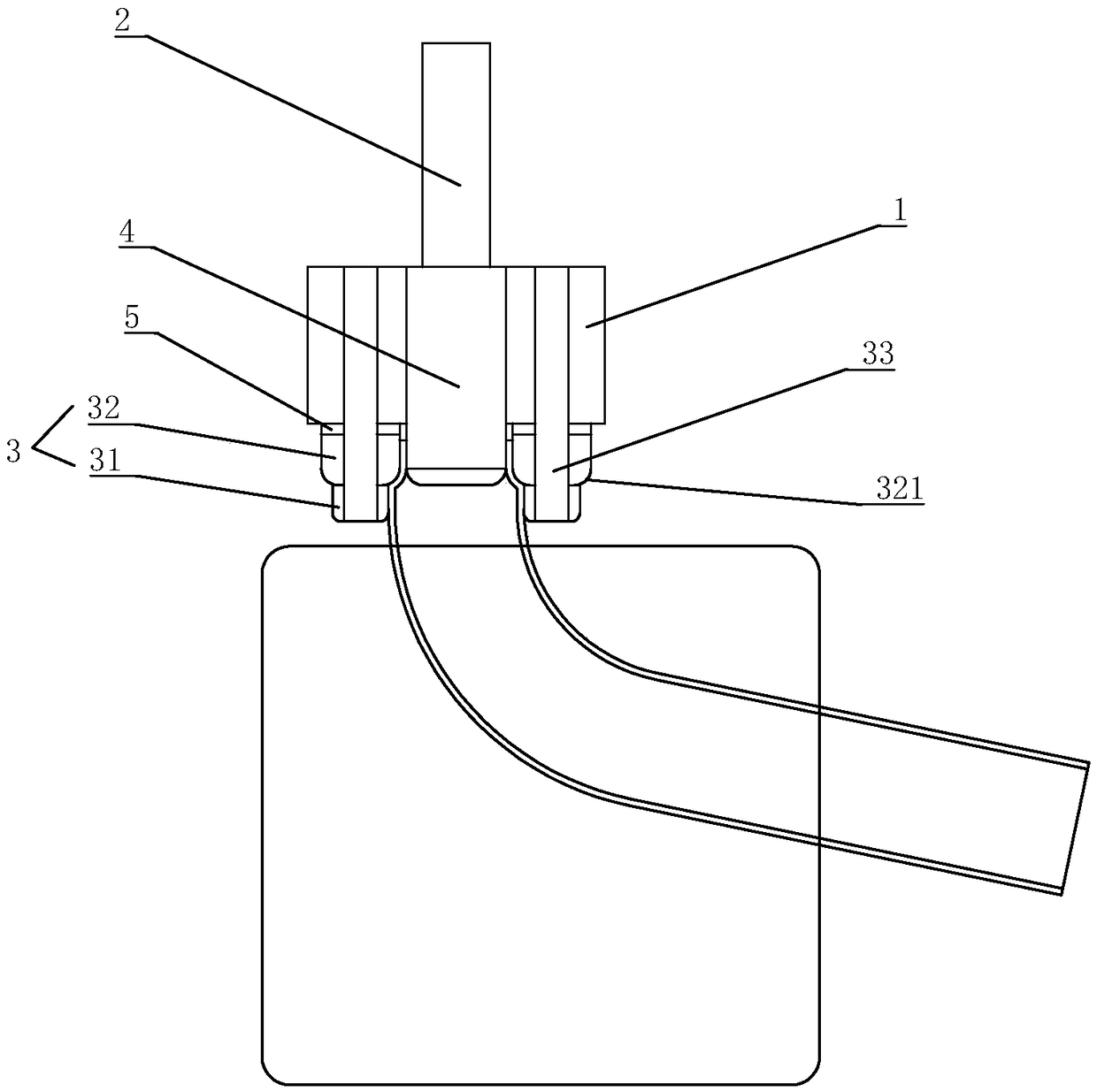
[0023] refer to Figure 1 to Figure 5 , a nozzle processing device of the present invention includes a rotary cutter, the rotary cutter includes a main cutter body 1, and a handle 2 is provided at one end of the main cutter body 1 to connect a driving device to drive the main cutter body 1 to rotate, so The other end of the main cutter body 1 is provided with a plurality of through holes around its rotation center, and a rotating shaft 33 is inserted in the through holes, and a working rotor 3 is installed on the rotating shaft 33 to rotate relatively; the working rotor 3 surrounds The center of rotation of the main cutter body 1 is evenly distributed in the circumferential direction, and the working rotor 3 and the main cutter body 1 are relatively rotatably connected, including a guide part and a forming part arranged above the guide part; the rotation center of the main cutter body 1 is fixed with an inner The rotating column 4 is further suitable for processing the nozzle ...


PUM


Abstract

The invention discloses a pipe orifice machining device. The pipe orifice machining device comprises a rotary cutter, wherein the rotary cutter comprises a main cutter body, one end of the main cutterbody is provided with a cutter handle so as to be connected with a driving device, and the driving device drives the main cutter body to rotate. A plurality of working rotors are arranged at the other end of the main cutter body around the rotation center of the main cutter body, and the working rotors are circumferentially and uniformly distributed. The working rotors comprise guiding portions and forming portions disposed above the guiding portions. A machining method of applying the pipe orifice machining device is to drive the main cutter body to rotate and move relative to pipe orificesto be machined so that the pipe orifices to be machined is guided by the guiding portions into the forming portions, the forming portions presses the pipe orifices for pipe shrinking or flanging; andmeanwhile, when the working rotors rotate along the rotation center of the main cutter body under the driving of the main cutter body, due to extrusion friction between the surfaces of the working rotors and the outer side walls of the pipe orifices, the working rotors rotate relative to the main cutter body and roll on the outer walls of the pipe orifices so as to prevent heat generated by dynamic friction, and the pipe orifices are prevented from overheating and burning out.

Description

technical field [0001] The invention relates to a device for shrinking and flanging the mouth of a stainless steel pipe and a processing method thereof. Background technique [0002] At present, in the nozzle shrinking of sanitary stainless steel water pipes, forming tools are often used to hard compress tubes, that is, the nozzles to be processed are rotated and extruded by a tool with a fixed contour shape to shrink the nozzles, but this process is only suitable for applications. On metals that are relatively soft and thin and easy to be squeezed and deformed, especially stainless steel pipes with a certain thickness cannot shrink and deform at all. However, various water leakage problems have appeared in thin tube products in practical applications, which affects the life and cost of the product; therefore, it is urgent to study a device that can also shrink and flang the nozzle of a stainless steel tube with a certain thickness. According to the method, the stainless st...

Claims


Application Information

Patent Timeline
Patent Type & Authority Applications(China)
IPC IPC(8): B21D19/04B21D19/12
CPCB21D19/046B21D19/12
Inventor 何祺晃
Owner KAIPING QILONG SANITARY WARE TECH CO LTD
Why Eureka
Try Eureka