Assembly method and device for LED box

A technology for LED cabinets and assembly devices, which is applied in assembly machines, metal processing equipment, manufacturing tools, etc., can solve problems such as site confusion, high personnel intensity, and damage to modules, so as to improve quality, improve production efficiency, The effect of reducing labor costs

Pending Publication Date: 2018-11-23
FUJIAN QIANGLI PHOTOELECTRICITY
View PDF10 Cites 1 Cited by
  • Summary
  • Abstract
  • Description
  • Claims
  • Application Information

AI Technical Summary

Problems solved by technology

[0004] In the existing method of operation, due to the operation of padding pearl cotton on the floor, personnel are required to hold the box, there are many types of boxes, and there are many types of fixtures, resulting in low yield, slow efficiency, confusion on site, and labor intensity. Advanced problems, and there are phenomena such as inconsistent methods, slow efficiency, uneven assembly, and prone to bruising modules

Method used


Image

  • Assembly method and device for LED box
  • Assembly method and device for LED box
  • Assembly method and device for LED box

Examples


Embodiment 1

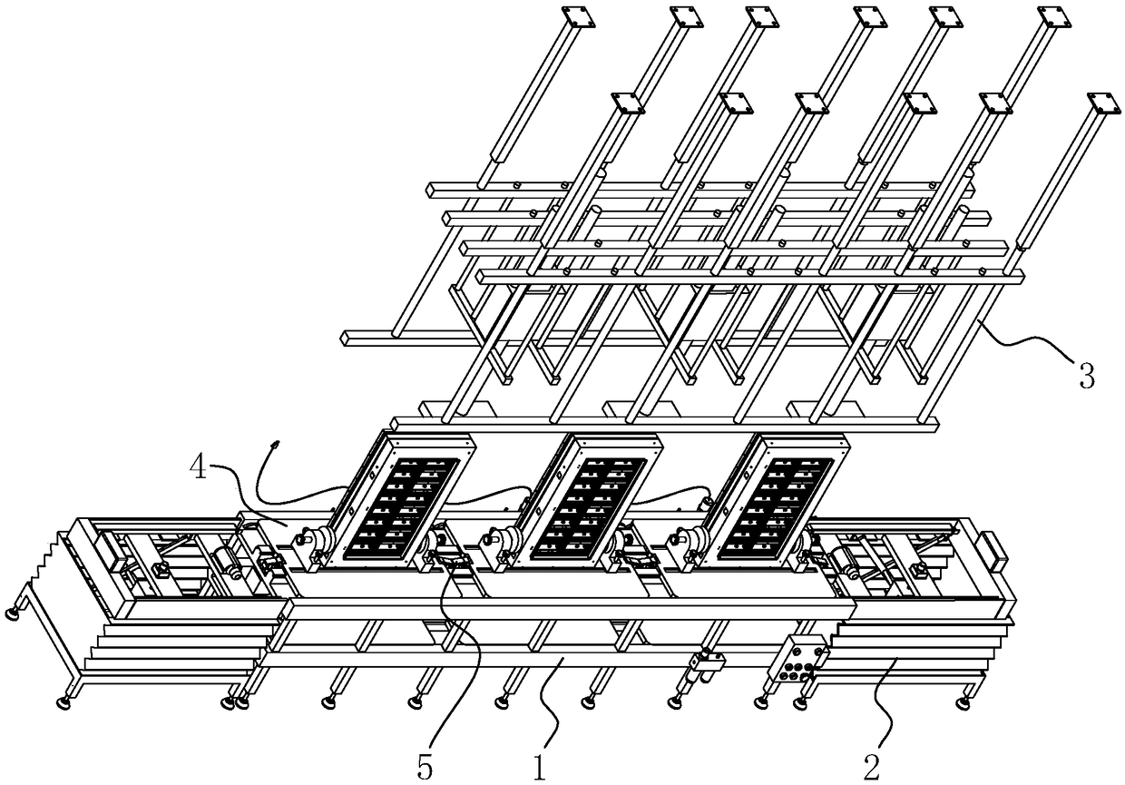
[0055] Embodiment 1: a kind of LED box assembly device, such as figure 1 As shown, it includes a transmission device 1 , an automatic pressing mechanism 3 , an automatic clamping mechanism 5 , a lifting mechanism 2 and a pallet 4 .

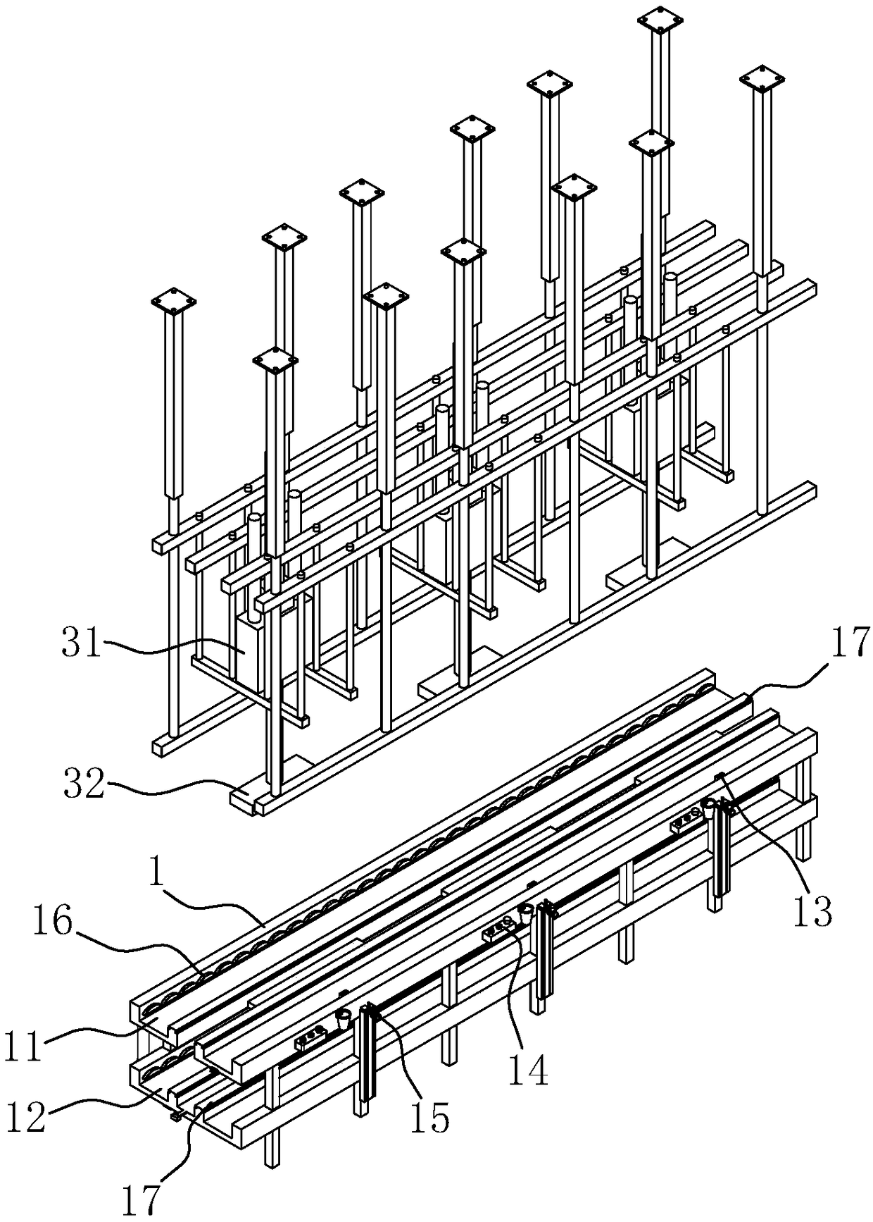
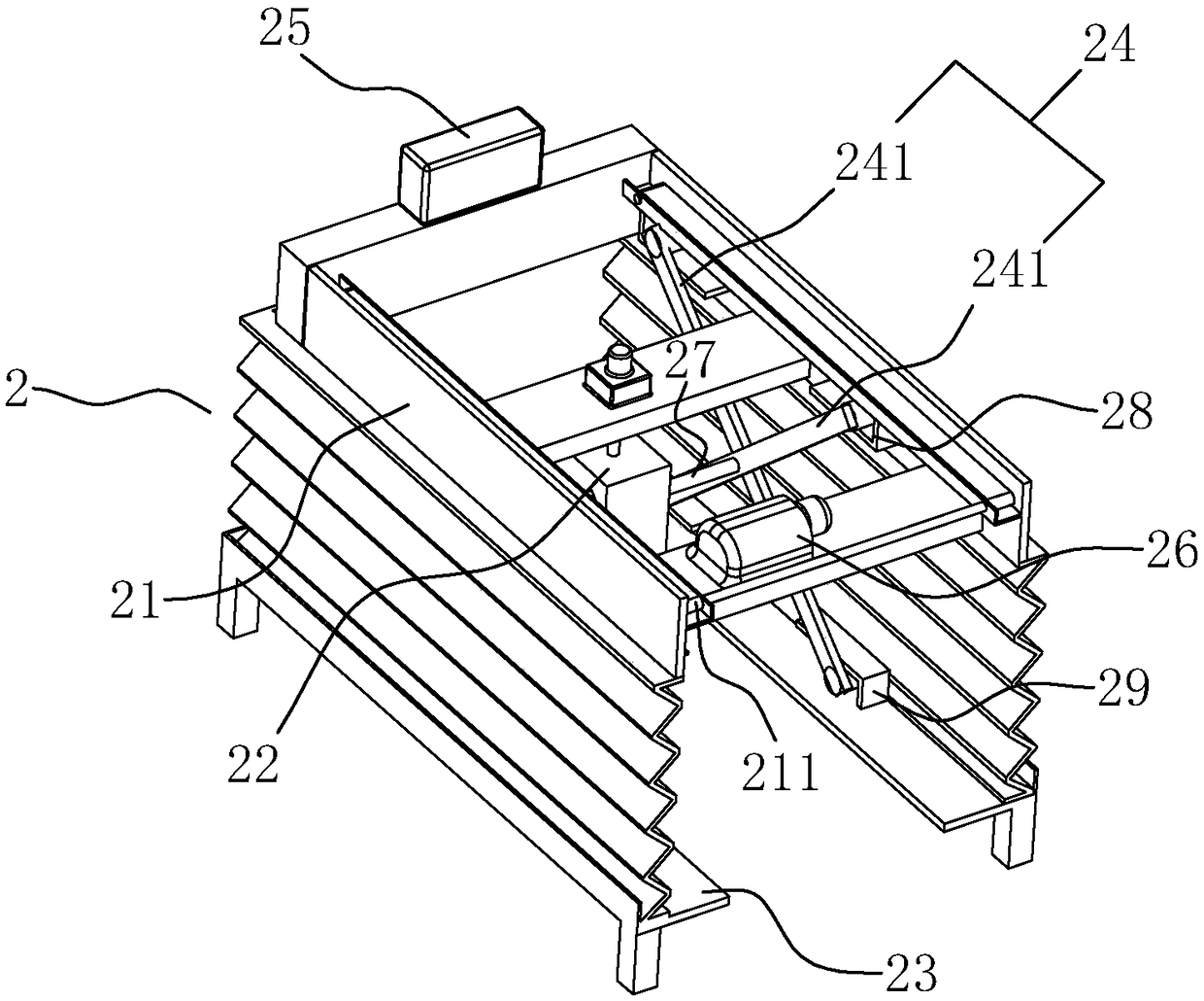
[0056] refer to figure 2 , The transmission device 1 is provided with upper and lower slideways, both of which can slide on the tray 4 . Such as figure 1 As shown, there are two lifting mechanisms 2, which are respectively arranged at the two ends of the transmission device 1, combined with the attached image 3 , the lifting device is provided with a conveyor belt and a lifting cylinder 22, and the lifting cylinder 22 is used to control the lifting of the conveyor belt. Wherein, when the conveyor belt rises to the top, it is connected with the upper slideway 11 on the transmission device 1 , and when the conveyor belt descends to the bottom, it is connected with the glideway 12 on the transmission device 1 .

[0057] The pallet 4 sent out fr...

Embodiment 2

[0076] Embodiment 2: A method for assembling an LED box, comprising:

[0077] S1. Inspection, check whether the electricity, gas and various mechanisms on the assembly device are normal;

[0078] S2, installation, after the detection is normal, the box body frame is placed on the pallet 4 on one of the lifting mechanisms 2, wherein, the lifting mechanism 2 is the initial position, and the clamping handle 412 is adjusted to make the two clamping parts 411 hold the box body frame fixed;

[0079] S3, transport to the station, after the installation is completed, start the motor 26 to pass the tray 4 into the upper slideway 11, after passing through the first sensor 13, the first group of automatic pressing mechanism 3 on the path starts, and the tray 4 on it starts The two stoppers 51 are raised, and when the tray 4 reaches the predetermined position, the stopper 51 abutting against the bottom of the tray 4 pushes out of the plane where the bottom of the tray 4 is under the acti...

Embodiment 3

[0085] Embodiment 3: as Figure 7 As shown, the difference from Embodiment 1 is that the limiting device 51 is an elastic telescopic rod 53 .


PUM


Abstract

The invention discloses an assembly method and device for an LED box. The device comprises trays for fixing the box, a conveying device for rays to slide on, an automatic pressing mechanism which is arranged above the conveying device and used for limiting the vertical direction of the box and two lifting mechanisms which are arranged at the two ends of the conveying device. Multiple automatic clamping mechanisms for clamping the trays are arranged on the conveying device, an upper slide way and a lower slide way are arranged on the conveying device, the lifting mechanisms in ascending and descending states are connected with the upper slide way and the lower slide way respectively, the situations of collision, scratch, static harm and the like of the box are avoided, the manual cost is effectively lowered, and the production efficiency and quality are improved.

Description

technical field [0001] The invention relates to the field of LED box groups, in particular to an LED box assembly method and device. Background technique [0002] The production process of LED cabinets involves the assembly of cabinet frames and modules, which are collectively referred to as cabinets after assembly. The assembly process of the box involves the assembly process, including the assembly of the module and the box frame. [0003] In the existing method, the pearl cotton is arranged on the floor, and then the limiting jig is placed on the surface of the pearl cotton body, the box frame is prepared, and the box frame is placed in the jig limit area, and then moved to the L row of the jig. After the reference side is placed in place, adjust the horizontal and vertical clamping blocks, and then tighten the handle after adjusting the appropriate position, prepare the corresponding module, use the positioning column set by the module to align with the positioning hole...

Claims


Application Information

Patent Timeline
IPC IPC(8): B23P21/00
CPCB23P21/00
Inventor 黄加园
Owner FUJIAN QIANGLI PHOTOELECTRICITY
Why Eureka
Try Eureka