Inner thimble for grinding hollow shaft

A technology of grinding and hollow shaft is applied in the field of inner thimble of hollow shaft grinding, which can solve the problems of wasting manpower and low processing efficiency, and achieve the effects of improving processing efficiency, simple structure, and quick and convenient positioning.

Pending Publication Date: 2018-11-23
JIANGNAN YIFAN MOTOR
View PDF6 Cites 0 Cited by
  • Summary
  • Abstract
  • Description
  • Claims
  • Application Information

AI Technical Summary

Problems solved by technology

[0003] The object of the present invention is to provide an inner thimble for hollow shaft grinding, so as to solve the problems of wasting manpower and low processing efficiency in the prior art hollow output shaft grinding

Method used


Image

  • Inner thimble for grinding hollow shaft
  • Inner thimble for grinding hollow shaft
  • Inner thimble for grinding hollow shaft

Examples


Embodiment Construction

[0016] The technical solutions of the present invention will be further described below in conjunction with the accompanying drawings and through specific implementation methods.

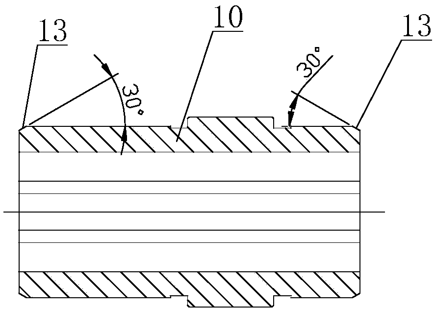
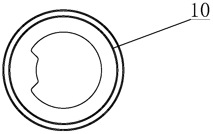
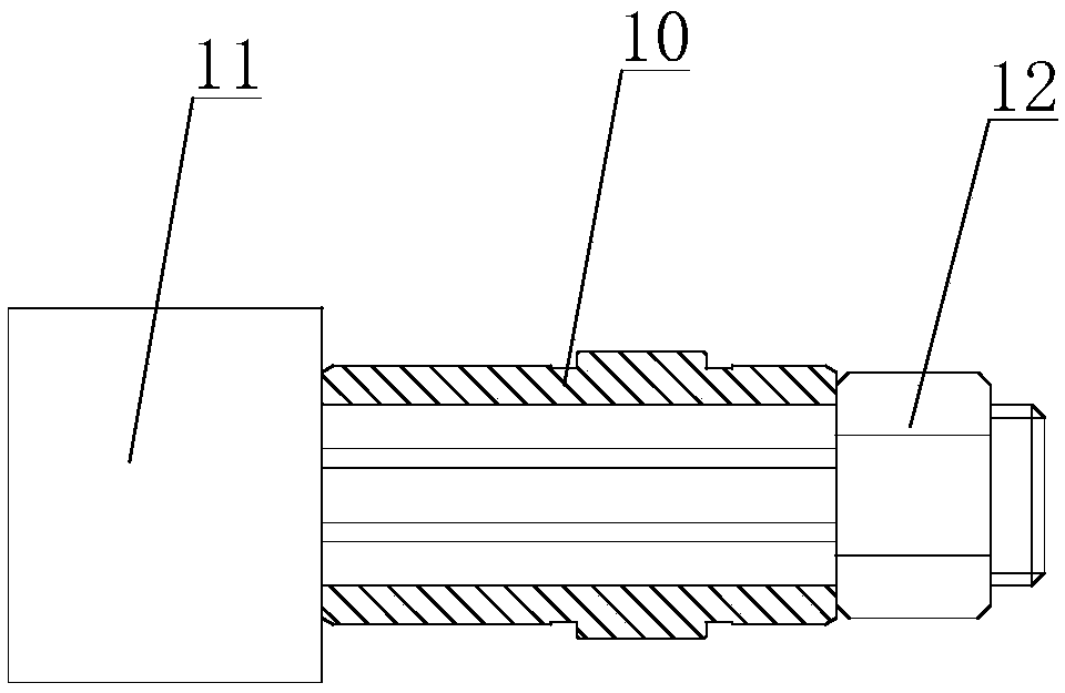
[0017] see Figure 4 and Figure 5 As shown, in this embodiment, an inner thimble used for hollow shaft grinding includes a thimble body 2, one end of the thimble body 2 has a Morse No. There is a hollow part 20, and the opening of the hollow part 20 is an inner cone angle 21 matching the chamfer 13 at the end of the hollow output shaft 10. The chamfer 13 is 30°, and the inner cone angle 21 is also 30°. Cooperating, when the hollow part 20 presses against the hollow output shaft 10, a horizontal and downward force will be generated on the end of the hollow output shaft 10, and the hollow output shaft 10 is conveniently positioned.

[0018] When positioning, use the two above-mentioned inner thimbles, connect the ejector rod bodies 2 of the two inner thimbles to the main shaft of the grinder and th...


PUM


Abstract

The invention discloses an inner thimble for grinding a hollow shaft. The inner thimble comprises a thimble rod body, wherein one end of the thimble rod has a Morse's taper, so that the end of the thimble rod can be sleeved into a grinding machine spindle or a grinding machine tailstock to be located; a hollow part is arranged at the other end of the thimble rod body, and the opening position of the hollow part is an inner taper angle which is matched with a chamfer at the end of a hollow output shaft; in location, the thimble rod body can abut against the chamfer at the end of the hollow output shaft through the inner taper angle to locate the hollow output shaft. The inner thimble for grinding the hollow shaft not only has a simple structure and an ingenious design, but also has quickness and convenience in location and can greatly improve the hollow output shaft processing efficiency under the premise that the processing quality is not affected.

Description

technical field [0001] The invention belongs to the shaft processing technology, in particular to an inner thimble used for hollow shaft grinding. Background technique [0002] see figure 1 and figure 2 as shown, figure 1 is a cross-sectional view of an existing hollow output shaft, figure 2 It is a side view of an existing hollow output shaft. It can be seen that the inner cavity of this kind of hollow output shaft 10 is irregular, and both ends are processed with chamfers 13, but the outer circle of the third gear is required to be ground, and it cannot be positioned through the inner hole. see image 3 as shown, image 3 It is a schematic diagram of the existing structure for positioning the hollow output shaft. At present, the common positioning method is to use the mandrel 11 for positioning, that is, the mandrel 11 passes through the inner hole of the hollow output shaft 10 and is fixed by the nut 12 in the radial direction. , although this method can meet the...

Claims


Application Information

Patent Timeline
Patent Type & Authority Applications(China)
IPC IPC(8): B24B5/02B24B5/35
CPCB24B5/02B24B5/35
Inventor 陈渊技
Owner JIANGNAN YIFAN MOTOR
Why Eureka
Try Eureka