Silicon wafer chamfering device

A technology of chamfering device and silicon wafer, which is applied in the direction of grinding drive device, grinding machine, grinding machine parts, etc. Effect

Inactive Publication Date: 2018-11-23
ZHENGZHOU JIZHI TECH CO LTD
View PDF1 Cites 0 Cited by
  • Summary
  • Abstract
  • Description
  • Claims
  • Application Information

AI Technical Summary

Problems solved by technology

[0005] The purpose of the present invention is to solve the problem in the prior art that it is difficult to perform individual chamfering on a certain area of ​​the silicon wafer, and provide a chamfering device that can perform chamfering on any edge of the silicon wafer

Method used


Image

  • Silicon wafer chamfering device
  • Silicon wafer chamfering device
  • Silicon wafer chamfering device

Examples


Embodiment 1

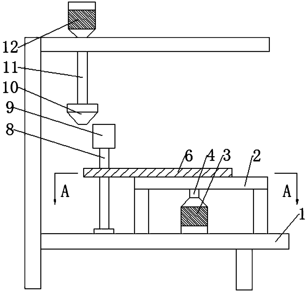
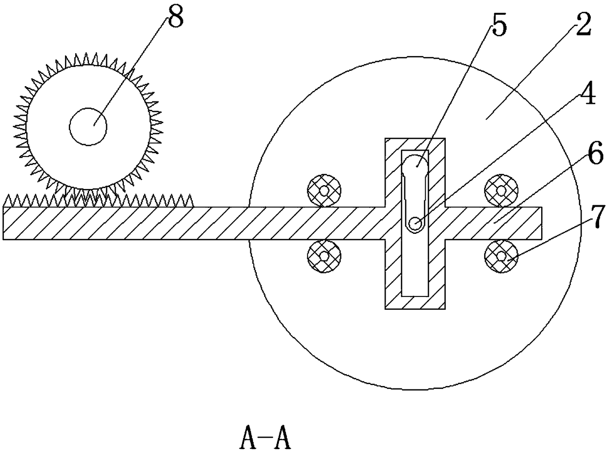
[0026] A silicon wafer chamfering device, comprising a mounting frame 1, a second motor 12 is arranged on the mounting frame 1, a grinding wheel 10 is connected to a second output shaft 11 of the second motor 12, and a fixing table 9 is arranged under the side of the grinding wheel 10, A rotating shaft 8 is also provided, and one end of the rotating shaft 8 is connected with the fixed table 9, and the other end of the rotating shaft 8 is installed on the mounting frame 1 through a bearing, and the rotating shaft 8 is also sleeved with gears; A motor 3, the output end of the first output shaft 4 of the first motor 3 is connected with a rotating rod 5, the rotating rod 5 is covered with a traverse rod 6, and the traverse rod 6 is placed on the placement table 2 and can slide arbitrarily, Limiting blocks 7 are also arranged on both sides of the traversing rod 6, and the limiting blocks 7 are fixed on the placement table 2. A cavity is provided inside the traversing rod 6, and the ...

Embodiment 2

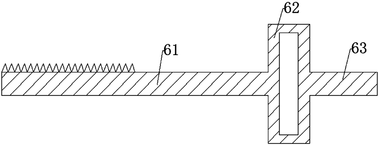
[0028] On the basis of Embodiment 1, the traversing rod 6 includes a first connecting rod 61, a connecting block 62, and a second connecting rod 63 connected in sequence. Teeth are provided on the side of the first connecting rod 61 corresponding to the position of the gear, and the middle part of the connecting block 62 A cavity is provided; four limit blocks 7 are provided, two limit blocks 7 are arranged on both sides of the first connecting rod 61, and the other two limit blocks 7 are arranged on both sides of the second connecting rod 63, four The limiting blocks 7 are distributed in a rectangular shape.

Embodiment 3

[0030] On the basis of the above embodiments, the limit block 7 is a pulley whose center is fixed on the placement platform 2 .


PUM


Abstract

The invention discloses a silicon wafer chamfering device and belongs to the technical field of chamfering equipment. The chambering device can perform chamfering on any edge part range of the a silicon wafer. The silicon wafer chamfering device comprises a mounting frame; a grinding wheel is disposed on the mounting frame; a fixing table is disposed on the side lower portion of the grinding wheel; a rotating shaft is further disposed on the mounting frame and connected with the fixing table; a gear is further disposed on the rotary shaft in a sleeving mode; a rotary rod is further connected to the mounting frame through a first motor; a transverse movement rod is disposed outside the rotary rod in a sleeving mode; limiting blocks are further disposed on the two sides of the transverse movement rod and fixed to the mounting frame; a cavity is formed inside the transverse movement rod; the rotary rod rotates in the cavity and can drive the transverse movement rod to reciprocate in a certain linear direction; teeth are further disposed in the position, corresponding to the gear, of the transverse movement rod; and the teeth of the transverse movement rod are engaged with the teeth ofthe gear. The reciprocating transverse movement rod drives the rotary shaft to perform reciprocating rotation in a changed direction, so that independent chambering effect on a certain position rangeof the silicon wafer is achieved, and the whole structure is novel and practical.

Description

technical field [0001] The invention belongs to the technical field of chamfering equipment, in particular to a silicon wafer chamfering device. Background technique [0002] Silicon wafers are a very important material basis in electronic information technology. With the continuous development of society, people's demand for the number of silicon wafers is gradually increasing, and the requirements for the shape of silicon wafers are also more diverse. In the production and processing process of silicon wafers, chamfering is one of the very important steps. In the prior art, for the chamfering of silicon wafers, generally, each corner of the silicon wafer can only be polished uniformly, but not for a specific corner. Polishing, it is difficult to meet people's diverse needs for silicon wafers. [0003] The patent application number CN201620669480.5 discloses a new type of high-efficiency silicon wafer chamfering machine. At present, the chamfering machines used by enterpr...

Claims


Application Information

Patent Timeline
Patent Type & Authority Applications(China)
IPC IPC(8): B24B27/00B24B9/06B24B41/06B24B41/02B24B47/12
CPCB24B27/0015B24B9/065B24B41/02B24B41/06B24B47/12
Inventor 张新卫郭小波
Owner ZHENGZHOU JIZHI TECH CO LTD
Why Eureka
Try Eureka