Partially-decoupled two-degree-of-freedom movement parallel mechanism

A degree of freedom, partial solution technology, applied in the field of robotics, can solve the problems of limited number of two-degree-of-freedom mobile decoupling parallel mechanisms, unfavorable processing and assembly, and difficulty in engineering realization, achieving good kinematic performance, low work center of gravity, Small error effect

Pending Publication Date: 2018-11-23
HUNAN TECHN COLLEGE OF WATER RESOURCES & HYDROPOWER
View PDF6 Cites 0 Cited by
  • Summary
  • Abstract
  • Description
  • Claims
  • Application Information

AI Technical Summary

Problems solved by technology

Among the decoupling mechanisms invented at present, the number of two-degree-of-freedom mobile decoupling parallel mechanisms is limited. The two-degree-of-freedom mobile decoupling parallel mechanism proposed in Chinese patent CN200510014391.3 can realize unconditional decoupling, but it is not conducive to processing and assembly; China The two-degree-of-freedom mobile decoupling parallel mechanism proposed by the patent CN200710171877.7 has good force characteristics, but the structure is slightly complicated; the two-degree-of-freedom positioning platf

Method used


Image

  • Partially-decoupled two-degree-of-freedom movement parallel mechanism

Examples


Embodiment Construction

[0017] The present invention will be further described below in conjunction with the accompanying drawings.

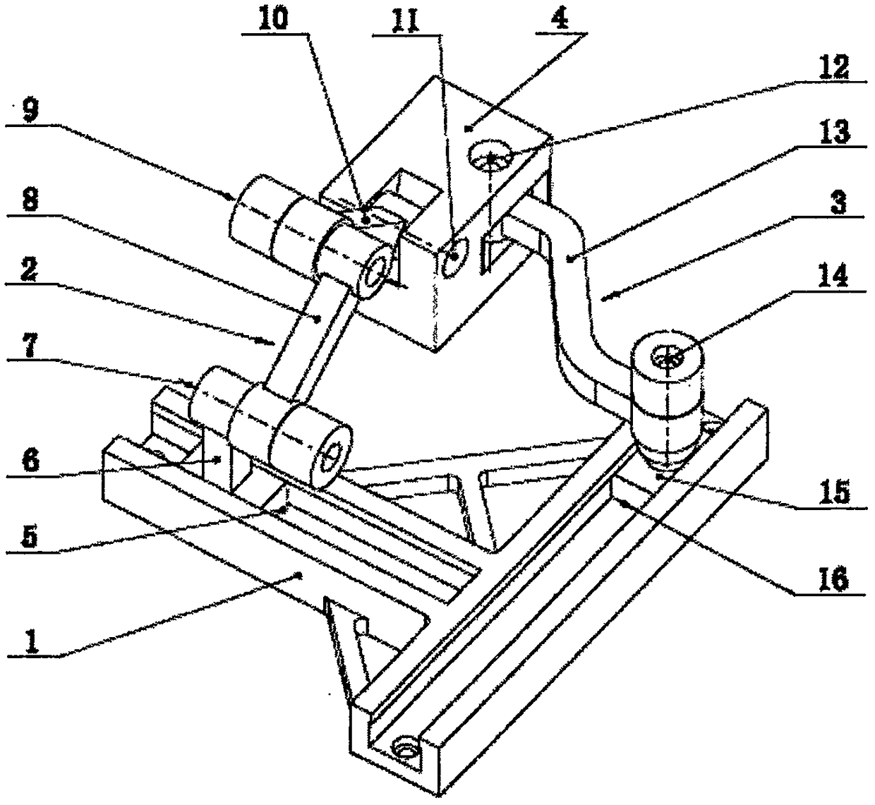
[0018] like figure 1 As shown, the partially decoupled two-degree-of-freedom mobile parallel mechanism of the present invention includes a moving platform 4, a fixed platform 1, and a first movement branch 2 and a second movement branch 3 respectively fixed between the movement platform 4 and the fixed platform 1 ; The first movement branch 2 includes the mobile pair P 1 5. The first slider 6. Rotating pair R 1 7. The first connecting rod 8, the rotating pair R29, the second connecting rod 10 and the rotating pair R 3 11. The second connecting rod 10 passes through the rotating pair R 3 11 is connected with the motion platform 4, and the revolving pair R 2 9 connects the second connecting rod 10 and the first connecting rod 8, and the rotating pair R 1 7 connects the first connecting rod 8 and the first slider 6, and the first slider 6 passes through the moving pa...


PUM


Abstract

The invention provides a partially-decoupled two-degree-of-freedom movement parallel mechanism. The partially-decoupled two-degree-of-freedom movement parallel mechanism is mainly composed of a movement platform, a fixed platform, and two movement branches which are fixedly connected between the two platforms respectively, wherein the first movement branch comprises three rotary pairs R1R2R3 withrotary axes which are parallel to one another, a movable pair P1, a first connection rod and a second connection rod which are used for connecting the three rotary pairs R1R2R3 and the movable pair P1, and a first sliding block; the second connection rod is connected with the movement platform through the rotary pair R3; the rotary pair R2 is connected with the second connection rod and the firstconnection rod; the rotary pair R1 is connected with the first connection rod and a first sliding block; the first sliding block is connected with the fixed platform through the movable pair P1; the second branch comprises two rotary pairs R4R5 with rotary axes which are parallel to each other, a movable pair P2, a third connection rod for connecting the rotary pairs R4R5 and the movable pair P2,and a second sliding block; the third connection rod is connected with the movement platform through the rotary pair R4; the rotary pair R5 is connected with the third connection rod and the second sliding block; the second sliding block is connected with the fixed platform through the movable pair P2. The partially-decoupled two-degree-of-freedom movement parallel mechanism has the advantages ofsimple structure, high rigidity, low working gravity center, small volume ratio, high precision and small errors; a movement part of the movement platform is partially decoupled so that the partially-decoupled two-degree-of-freedom movement parallel mechanism has good kinematics performance and flexibility.

Description

technical field [0001] The invention relates to the field of robots, in particular to a two-degree-of-freedom parallel mechanism. Background technique [0002] Compared with the series mechanism, the parallel mechanism is a multi-branched closed-loop method. It has high rigidity, high speed, compact structure, small motion inertia, small influence of cumulative error, and high precision. Unique application; while the parallel mechanism with few degrees of freedom has the advantages of simple structure, low manufacturing cost and easy control, etc., it is very useful in the industrial field. Great application prospects. [0003] Decoupling is one of the hotspots in the academic field of mechanisms today. If the movement of the mechanism can be decoupled, its working space will be expanded, and the control will be easy, and higher motion precision can be achieved. It has certain effects on the movement control and trajectory planning of the mechanism significance. Among the...

Claims


Application Information

Patent Timeline
IPC IPC(8): B25J9/00
CPCB25J9/0036Y02E10/50
Inventor 战丽娜姜潮
Owner HUNAN TECHN COLLEGE OF WATER RESOURCES & HYDROPOWER
Why Eureka
Try Eureka