Novel rail car air duct module integration structure

A technology for rail vehicles and air ducts, which is applied in the field of integrated structure of new rail vehicle air ducts, and can solve problems such as inconvenient maintenance, multiple interfaces, troublesome installation and maintenance, etc.

Pending Publication Date: 2018-11-23
QINGDAO VICTALL RAILWAY CO LTD
View PDF1 Cites 6 Cited by
  • Summary
  • Abstract
  • Description
  • Claims
  • Application Information

AI Technical Summary

Problems solved by technology

[0002] The existing rail vehicle body includes modules such as car body frame, air duct, middle roof, side roof, lighting and ventilation grille. Each module needs to be installed and connected to the car body frame separately, so the car body frame needs to provide a large number of installation interfaces , the body frame is highly complex
Each module needs to be installed on the car body frame separately, and each module has its own mounting bracket or fixing piece, so there are many types of materials used, heavy weight, and a lot of space
In addition, when each module of the existing rail vehicle is installed separately, the installation of each module must eliminate the deformation of the car body, and there are many interfaces, making the installation complicated
After installation, each module affects each other. When repairing a single position, it is often necessary to dismantle adjacent components to realize it. The repair process is complicated.
[0003] The integrated module in the rail vehicle in the prior art only int...

Method used


Image

  • Novel rail car air duct module integration structure
  • Novel rail car air duct module integration structure
  • Novel rail car air duct module integration structure

Examples


Embodiment Construction

[0029] The present invention will be further described in detail below in conjunction with the accompanying drawings and specific embodiments.

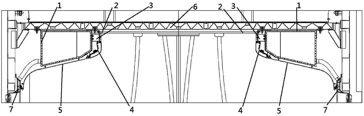
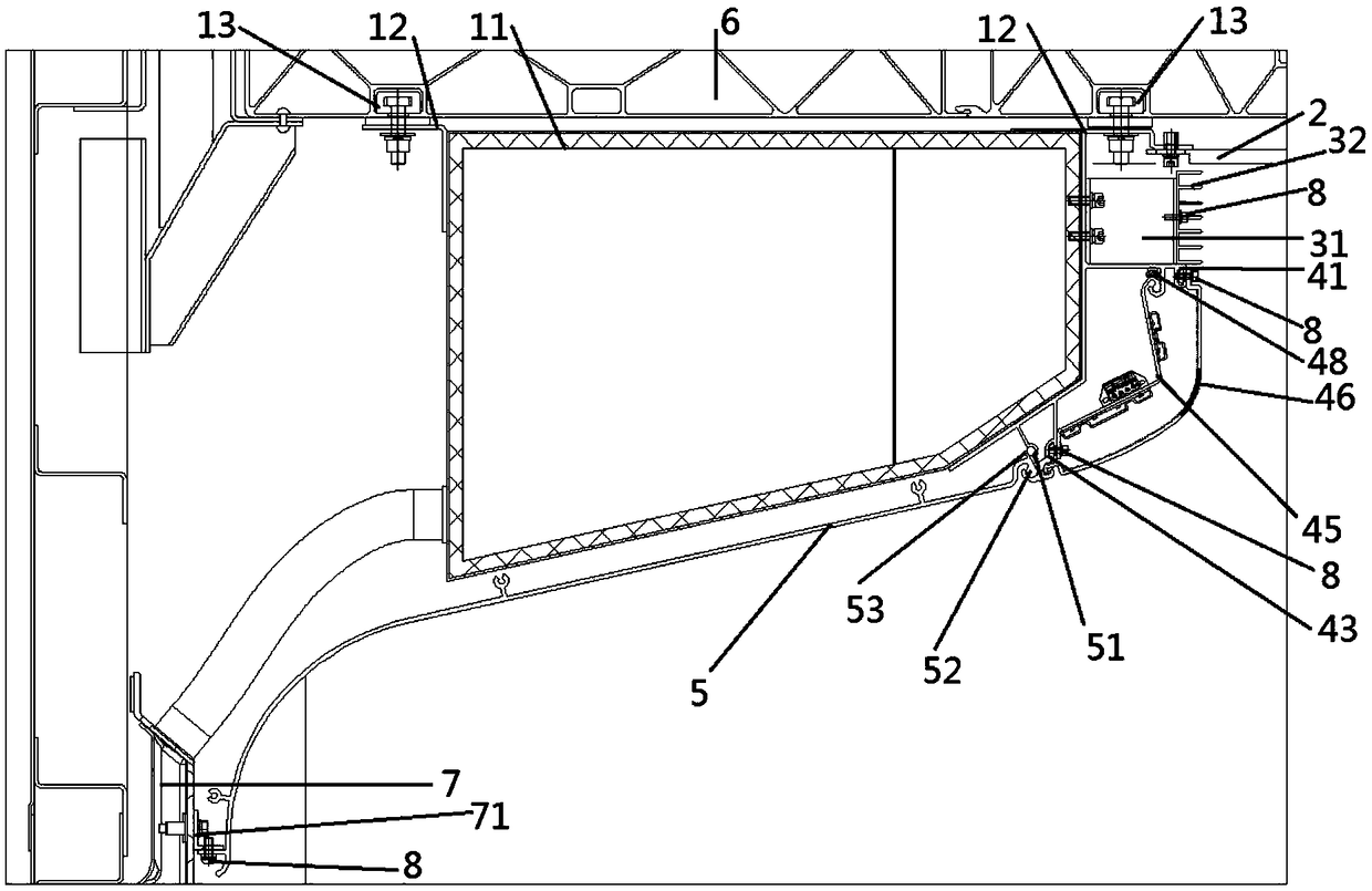
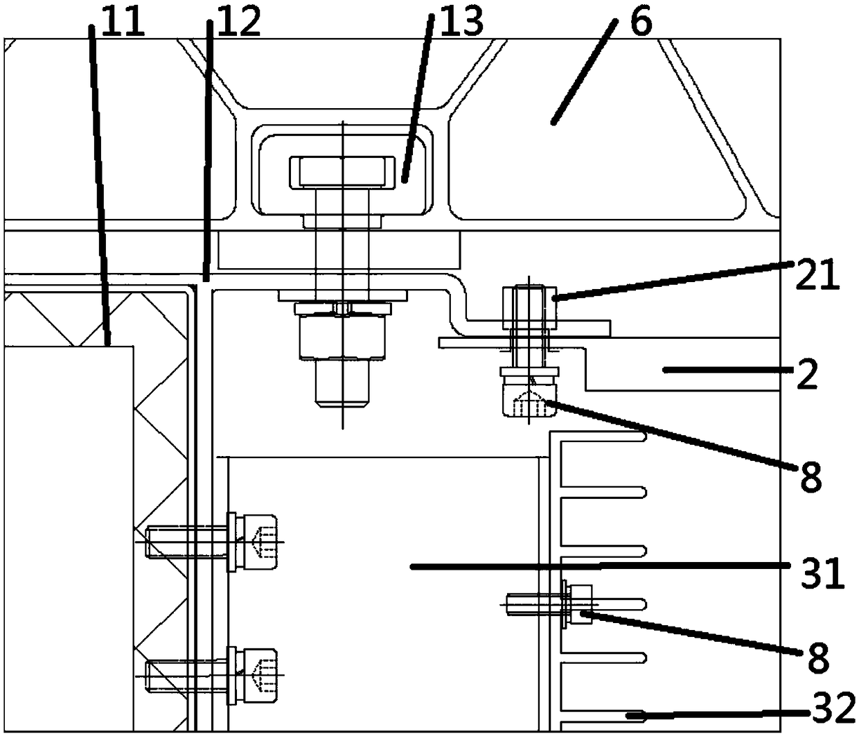
[0030] refer to Figure 1-7Among them, a new rail vehicle air duct module integrated structure, including air duct module 1, middle roof 2, ventilation grille 3, lighting device 4 and side roof 5; said air duct module 1, middle roof 2, ventilation grille 3. The lighting device 4 and the side top plate 5 are arranged symmetrically on the left and right sides of the car body frame 6; the upper side of the air duct module 1 is fixedly connected with the car body frame 6, and the inner side of the air duct module 1 is installed with the middle roof plate 2 and the ventilation system. The grille 3 and the lighting device 4, the side top plate 5 is installed on the lower side of the air duct module 1; The outside is fixedly connected with the air duct module 1; the lower side of the ventilation grille 3 is provided with a lighting device 4...


PUM


Abstract

The invention discloses a novel rail car air duct module integration structure. According to the technical scheme, the novel rail car air duct module integration structure comprises an air duct module, a middle top plate, a ventilating grid, a lighting device and a side top plate. The upper side of the air duct module is fixedly connected with a car body frame, the upper end of the inner side of the air duct module is fixedly connected with the middle top plate, the ventilating grid is arranged on the lower side of the middle top plate, and the outer side of the ventilating grid is fixedly connected with the air duct module. The lighting device is arranged on the lower side of the ventilating grid, and the upper end and the lower end of the lighting device are both fixedly connected with the air duct module. The side top plate is arranged on the lower side of the lighting device, the upper end of the side top plate is fixedly connected with the air duct module, the outer side of the lower end of the side top plate is fixedly connected with a side wall frame, and the side wall frame is fixedly connected with the car body frame. The air duct module, the middle top plate, the side topplate, the ventilating grid and the lighting device are installed in an integrated mode, then the air duct module is installed on the car body frame, the complexity degree of the car body structure is lowered, and the structure is easy and convenient to install and convenient to maintain.

Description

technical field [0001] The invention relates to the field of rail vehicle body structures, in particular to a novel rail vehicle air duct integration structure. Background technique [0002] The existing rail vehicle body includes modules such as car body frame, air duct, middle roof, side roof, lighting and ventilation grille. Each module needs to be installed and connected to the car body frame separately, so the car body frame needs to provide a large number of installation interfaces , the body frame is highly complex. Each module needs to be installed on the car body frame separately, and each module has its own mounting bracket or fixing piece, so there are many types of materials used, heavy weight, and a lot of space. In addition, when each module of the existing rail vehicle is installed separately, the installation of each module must eliminate the deformation of the car body, and there are many interfaces, making the installation complicated. After installation,...

Claims


Application Information

Patent Timeline
IPC IPC(8): B61D27/00B61D17/14B61D29/00
CPCB61D27/0018B61D17/14B61D29/00
Inventor 王耀武刘皓锋杨昭兴胡国鹏孙健
Owner QINGDAO VICTALL RAILWAY CO LTD
Why Eureka
Try Eureka